Difference between revisions of "Documentation Talk:Reference Section 3"
Le Forgeron (talk | contribs) (→Camera: adding images for some cameras, and info about their settings) |
Le Forgeron (talk | contribs) |
||
| (15 intermediate revisions by 2 users not shown) | |||
| Line 1: | Line 1: | ||
| − | |||
| − | |||
| − | |||
| − | |||
| − | |||
| − | |||
| − | |||
| − | |||
| − | |||
| − | |||
| − | |||
| − | |||
| − | |||
| − | |||
| − | |||
| − | |||
| − | |||
| − | |||
| − | |||
| − | |||
| − | |||
| − | |||
| − | |||
| − | |||
| − | |||
| − | |||
| − | |||
| − | |||
| − | |||
| − | |||
| − | |||
| − | |||
| − | |||
| − | |||
| − | |||
| − | |||
| − | |||
| − | |||
| − | |||
| − | |||
| − | |||
| − | |||
| − | |||
| − | |||
| − | |||
| − | |||
| − | |||
| − | |||
| − | |||
| − | |||
| − | |||
| − | |||
| − | |||
| − | |||
| − | |||
| − | |||
| − | |||
| − | |||
| − | |||
| − | |||
| − | |||
| − | |||
===Camera=== | ===Camera=== | ||
====Fisheye==== | ====Fisheye==== | ||
| − | [[ | + | <table class="centered" width="660px" cellpadding="0" cellspacing="10"> |
| + | <tr> | ||
| + | <td> | ||
| + | [[Image:RefImgCameraViewFisheye.png|center|640px<!--center--->]] | ||
| + | </td> | ||
| + | </tr> | ||
| + | <tr> | ||
| + | <td> | ||
| + | <p class="caption">The fisheye projection</p> | ||
| + | </td> | ||
| + | <td> | ||
| + | </td> | ||
| + | </tr> | ||
| + | </table> | ||
| + | <p>Length of direction, up and right are irrelevant. Angle is the important setting and can go up to 360.</p> | ||
| − | |||
====omnimax==== | ====omnimax==== | ||
| − | [[ | + | <table class="centered" width="660px" cellpadding="0" cellspacing="10"> |
| + | <tr> | ||
| + | <td> | ||
| + | [[Image:RefImgCameraViewOmnimax.png|center|640px<!--center--->]] | ||
| + | </td> | ||
| + | </tr> | ||
| + | <tr> | ||
| + | <td> | ||
| + | <p class="caption">The omnimax projection</p> | ||
| + | </td> | ||
| + | <td> | ||
| + | </td> | ||
| + | </tr> | ||
| + | </table> | ||
| + | <p>Angle is irrelevant. The relative length of up and right are important.</p> | ||
| − | |||
====orthographic==== | ====orthographic==== | ||
| − | [[ | + | <table class="centered" width="660px" cellpadding="0" cellspacing="10"> |
| − | + | <tr> | |
| − | Length of direction is irrelevant unless angle is used. Lengths of up and right define the dimensions of the view. Angle can be used (as long as less than 180) and will override the length of right and up (the aspect ratio between up and right will be kept nevertheless) with a scope of a perspective camera with the same direction and angle. | + | <td> |
| + | [[Image:RefImgCameraViewOrthographic.png|center|640px<!--center--->]] | ||
| + | </td> | ||
| + | </tr> | ||
| + | <tr> | ||
| + | <td> | ||
| + | <p class="caption">The orthographic projection</p> | ||
| + | </td> | ||
| + | <td> | ||
| + | </td> | ||
| + | </tr> | ||
| + | </table> | ||
| + | <p>Length of direction is irrelevant unless angle is used. Lengths of up and right define the dimensions of the view. Angle can be used (as long as less than 180) and will override the length of right and up (the aspect ratio between up and right will be kept nevertheless) with a scope of a perspective camera with the same direction and angle.</p> | ||
====panoramic==== | ====panoramic==== | ||
| − | [[ | + | <table class="centered" width="660px" cellpadding="0" cellspacing="10"> |
| + | <tr> | ||
| + | <td> | ||
| + | [[Image:RefImgCameraViewPanoramic.png|center|640px<!--center--->]] | ||
| + | </td> | ||
| + | </tr> | ||
| + | <tr> | ||
| + | <td> | ||
| + | <p class="caption">The panoramic projection</p> | ||
| + | </td> | ||
| + | <td> | ||
| + | </td> | ||
| + | </tr> | ||
| + | </table> | ||
| + | <p>Angle is irrelevant. The relative length of direction, up and right are important as they defines the lengths of the 3 axis of the ellipsoid. With identical length and orthogonal vectors (both strongly recommended, unless used on purpose), it's identical to a spherical camera with angle 180,90.</p> | ||
| − | |||
====perspective==== | ====perspective==== | ||
| − | [[ | + | <table class="centered" width="660px" cellpadding="0" cellspacing="10"> |
| + | <tr> | ||
| + | <td> | ||
| + | [[Image:RefImgCameraViewPerspective.png|center|640px<!--center--->]] | ||
| + | </td> | ||
| + | </tr> | ||
| + | <tr> | ||
| + | <td> | ||
| + | <p class="caption">The perspective projection</p> | ||
| + | </td> | ||
| + | <td> | ||
| + | </td> | ||
| + | </tr> | ||
| + | </table> | ||
| + | <p>Angle can be used as long as less than 180 and will recompute the length of right and up using direction, while keeping the aspect ratio between up and right. </p> | ||
| − | |||
====spherical==== | ====spherical==== | ||
| − | [[image: | + | <table class="centered" width="660px" cellpadding="0" cellspacing="10"> |
| + | <tr> | ||
| + | <td> | ||
| + | [[Image:RefImgCameraViewSpherical.png|center|640px<!--center--->]] | ||
| + | </td> | ||
| + | </tr> | ||
| + | <tr> | ||
| + | <td> | ||
| + | <p class="caption">The spherical projection</p> | ||
| + | </td> | ||
| + | <td> | ||
| + | </td> | ||
| + | </tr> | ||
| + | </table> | ||
| + | <p>Lengths of direction, up and right vectors are irrelevant. Angle is the important setting, and it gets two values separated by a comma: the first is the horizontal angle, the second is the vertical angle. Both values can reach 360. If the second value is missing, it get half the value of the first.</p> | ||
| + | |||
| + | |||
| + | ---- | ||
| + | here after some editorial changes that might need review. | ||
| + | --[[User:Le Forgeron|Le Forgeron]] 09:12, 2 October 2011 (UTC) | ||
| + | * in section Placing the Camera (3.3.1.1) | ||
| + | The POV-Ray camera has ten different models, | ||
| + | |||
| + | well, it is not ten (10). If cylindrical & mesh are counted for 1 each, there is 9. | ||
| + | perspective (1), orthographic (2), mesh(3), fisheye (4), ultra wide angle (5), omnimax(6), panoramic (7), cylindrical (8), spherical (9) | ||
| + | (notice: I used the order and number of sub-sections) | ||
| + | If cylindrical and mesh are counted as many (4 cylindrical, 1 or 4 mesh), it is either 12 or 15. | ||
| + | |||
| + | * in section Orthographic camera (3.3.1.2.2, end of section) | ||
| + | |||
| + | If objects are too close to the camera location they may disappear. Too close here means, behind the orthographic camera projection plane (the plane that goes through the '''look_at''' point). | ||
| + | |||
| + | It's not look_at, but '''location''' point . | ||
| + | |||
| + | * all camera type: it would be nice to get a small sampling (i.e. an image about a fourth of the width of column, so as to have the text on the side) which illustrate each type of camera. Do we have a "typical scene" ? | ||
| + | |||
| + | * bokeh pigment would get clearer with pictures inspired from the megapov documentation.(pigment & result) (and from a strict vocabulary point, bokeh is not that kind of usage... well, should I trust wikipedia on bokeh ?) | ||
| + | --[[User:Le Forgeron|Le Forgeron]] 09:12, 2 October 2011 (UTC) | ||
| + | |||
| + | * Thanks for the follow up, the 1st two technical corrections you listed above have been done. Maybe you could expand a bit on the last two items as I'm not clear on what you are suggesting. | ||
| + | --[[User:Jholsenback|jholsenback]] 14:27, 2 October 2011 (UTC) | ||
| + | |||
| + | I do like the layout with a small image on a side, and the paragraph on the side of the image (once demonstrated in your page). I would be delighted (as a reader), when reading about the camera, to have, inline, an example (it's a bit of lazyness, as reading the text should allow the reader to "see" the kind of view. | ||
| + | |||
| + | [[image:CameraSampleCylinder_1.jpg]] | ||
| + | [[image:CameraSampleCylinder_2.jpg]] | ||
| + | [[image:CameraSampleCylinder_3.jpg]] | ||
| + | [[image:CameraSampleCylinder_4.jpg]] | ||
| + | [[image:CameraSampleFisheye.jpg]] | ||
| + | [[image:CameraSampleOmnimax.jpg]] | ||
| + | [[image:CameraSampleOrthographic.jpg]] | ||
| + | [[image:CameraSamplePanoramic.jpg]] | ||
| + | [[image:CameraSamplePerspective.jpg]] | ||
| + | [[image:CameraSampleSpherical.jpg]] | ||
| + | [[image:CameraSampleUltrawideangle.jpg]] | ||
| + | (I'm missing a mesh camera illustration... and it's probably not the best scene to show) | ||
| + | |||
| + | Regarding bokeh, I will try to use the megapov documentation to do my own illustration. | ||
| + | |||
| + | --[[User:Le Forgeron|Le Forgeron]] 18:56, 2 October 2011 (UTC) | ||
| + | |||
| + | * I played around with a couple scenarios and I'm not having much luck. The size of these images seems a bit small (150x150px), so they don't even really make the grade when it comes to being useful. Maybe it's my <em>old</em> eyes. The smallest images we have are the panels in the [[Documentation:Tutorial Section 3.7#Radiosity without conventional lighting|radiosity tutorial]] and they are 220px wide. Keep in mind the widest image we can use without overflowing the set page boundary is 680px. Oh and I guess you didn't notice that I had to rename <strong>ALL</strong> your first round images to conform to the naming convention. I did <em>not</em> rename these last ones, as somehow I think we can do just a tad better. | ||
| + | --[[User:Jholsenback|jholsenback]] 11:11, 4 October 2011 (UTC) | ||
| + | |||
| + | For the naming convention, I hope these new pictures are more conform. (where is the relevant text ? Did I miss it ?) | ||
| + | (I'm also always afraid to specify an existing name) | ||
| + | Maybe a section starting with: | ||
| + | |||
| + | [[image:RefImgCameraSampleScene.jpg]] | ||
| + | the full world, with the camera inside the grids, looking at the green and white sphere. | ||
| + | |||
| + | Then either with caption isuing : | ||
| + | |||
| + | [[image:RefImgCameraSamplecylinder_1.png]] | ||
| + | |||
| + | [[image:RefImgCameraSamplecylinder_2.png]] | ||
| + | |||
| + | [[image:RefImgCameraSamplecylinder_3.png]] | ||
| + | |||
| + | [[image:RefImgCameraSamplecylinder_4.png]] | ||
| + | |||
| + | [[image:RefImgCameraSamplefisheye.png]] | ||
| + | |||
| + | [[image:RefImgCameraSampleomnimax.png]] | ||
| + | |||
| + | [[image:RefImgCameraSampleorthographic.png]] | ||
| + | |||
| + | [[image:RefImgCameraSamplepanoramic.png]] | ||
| + | |||
| + | [[image:RefImgCameraSampleperspective.png]] | ||
| + | |||
| + | [[image:RefImgCameraSamplespherical.png]] | ||
| + | |||
| + | [[image:RefImgCameraSampleultra_wide_angle.png]] | ||
| + | |||
| + | |||
| + | or if big picture are better (me too, I have issue with small view) | ||
| + | |||
| + | [[image:RefImgCameraSamplecylinder_1.jpg]] | ||
| + | |||
| + | [[image:RefImgCameraSamplecylinder_2.jpg]] | ||
| + | |||
| + | [[image:RefImgCameraSamplecylinder_3.jpg]] | ||
| + | |||
| + | [[image:RefImgCameraSamplecylinder_4.jpg]] | ||
| + | |||
| + | [[image:RefImgCameraSamplefisheye.jpg]] | ||
| + | |||
| + | [[image:RefImgCameraSampleomnimax.jpg]] | ||
| + | |||
| + | [[image:RefImgCameraSampleorthographic.jpg]] | ||
| + | |||
| + | [[image:RefImgCameraSamplepanoramic.jpg]] | ||
| + | |||
| + | [[image:RefImgCameraSampleperspective.jpg]] | ||
| + | |||
| + | [[image:RefImgCameraSamplespherical.jpg]] | ||
| + | |||
| + | [[image:RefImgCameraSampleultra_wide_angle.jpg]] | ||
| + | |||
| + | --[[User:Le Forgeron|Le Forgeron]] 13:05, 9 October 2011 (UTC) | ||
| + | |||
| + | * Below is a preliminary stab at what I'm fairly sure will be close to what I'd like to use. The larger images allow for greater flexibility, as I can use a scale factor to fit the two image panel set up. View the source if you're curious about details. Much better, Don't you agree? | ||
| + | |||
| + | --[[User:Jholsenback|jholsenback]] 15:33, 9 October 2011 (UTC) | ||
| + | |||
| + | ** I like it. Best of both worlds: small pictures in text that can be enlarged for the details. | ||
| + | ** I would nevertheless introduce the global view (RefImgCameraSampleScene.jpg) at the beginning of the camera section, as it might be of interest to know where the various objects are in 3D. (3 boxes & 3 spheres of different colours, two-half-infinite planes, a sphere as target and a skysphere). Do you want the code for the scene & cameras ? | ||
| + | |||
| + | --[[User:Le Forgeron|Le Forgeron]] 11:29, 10 October 2011 (UTC) | ||
| + | |||
| + | =====Perspective projection===== | ||
| + | <!--<indexentry primary "perspective">---><!--<indexentry "projection, perspective">---> | ||
| + | |||
| + | <p>The <code>perspective</code> keyword specifies the default perspective camera which simulates the classic pinhole camera. The <em>horizontal</em> viewing angle is either determined by the ratio between the length of the <code>direction</code> vector and the length of the <code>right</code> vector or by the optional keyword <code>angle</code>, which is the preferred way. The viewing angle has to be larger than 0 degrees and smaller than 180 degrees.</p> | ||
| + | |||
| + | <table class="centered" width="670px" cellpadding="0" cellspacing="10"> | ||
| + | <tr> | ||
| + | <td> | ||
| + | [[Image:RefImgCameraViewPerspective.png|center|320px<!--leftpanel--->]] | ||
| + | </td> | ||
| + | <td> | ||
| + | [[Image:RefImgCameraSampleperspective.jpg|center|320px<!--rightpanel--->]] | ||
| + | </td> | ||
| + | </tr> | ||
| + | <tr> | ||
| + | <td> | ||
| + | <p class="caption">The perspective projection diagram</p> | ||
| + | </td> | ||
| + | <td> | ||
| + | <p class="caption">A perspective camera sample image</p> | ||
| + | </td> | ||
| + | </tr> | ||
| + | </table> | ||
| + | <p class="Note"><strong>Note:</strong> The <code>angle</code> keyword can be used as long as less than 180 degrees. It recomputes the length of right and up vectors using <code>direction</code>. The proper aspect ratio between the <code>up</code> and <code>right</code> vectors is maintained.</p> | ||
| + | |||
| + | ====Addition of cylinder schema==== | ||
| + | |||
| + | [[Image:RefImgCameraViewCylinder1.png]] | ||
| + | |||
| + | [[Image:RefImgCameraViewCylinder2.png]] | ||
| + | |||
| + | [[Image:RefImgCameraViewCylinder3.png]] | ||
| + | |||
| + | [[Image:RefImgCameraViewCylinder4.png]] | ||
| + | |||
| + | --[[User:Le Forgeron|Le Forgeron]] 10:38, 11 October 2011 (UTC) | ||
| + | |||
| + | ====Addition of ultra wide angle schema==== | ||
| + | |||
| + | [[Image:RefImgCameraViewUltrawideangle.png]] | ||
| + | |||
| + | the aspect ratio of lengths of up/right is used to provide the vertical angle from the horizontal angle (so that the ratio of vertical angle on horizontal angle is identical to the ratio of the length of up on length of right). | ||
| + | |||
| + | when the ratio is one, a square is wrapped on a madeleine (quartic surface x²+y²+z² = x²y² +1 : the section on z=0 is a square, the sections on x=0 or y=0 are circle. sections parallel to x=0 or y=0 are ellipses) | ||
| + | |||
| + | when the ratio is not one, the bigger angle get obviously wrapped further. | ||
| + | |||
| + | When the angle reach 180, the border meet the square section. | ||
| + | |||
| + | The angle can go above 180, in which cases, when both (vertical and horizontal) angles are above 180, the parts around the corners of the square section start to be wrapped more than once. | ||
| + | |||
| + | A classical usage is using an angle of 360 but with a up/right ratio of 1/2 ("up 10*y" , "right 20*x"). it keep the top of the picture as the zenith and the bottom of the picture as the nadir, avoiding perception issues, and giving a full 360° view. | ||
| − | + | --[[User:Le Forgeron|Le Forgeron]] 14:02, 11 October 2011 (UTC) | |
Latest revision as of 14:15, 11 October 2011
Camera
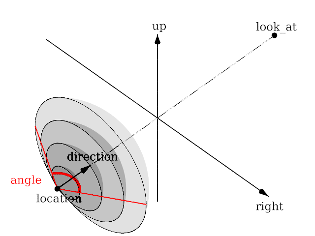
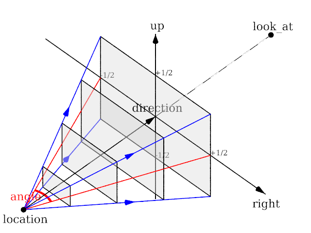
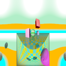
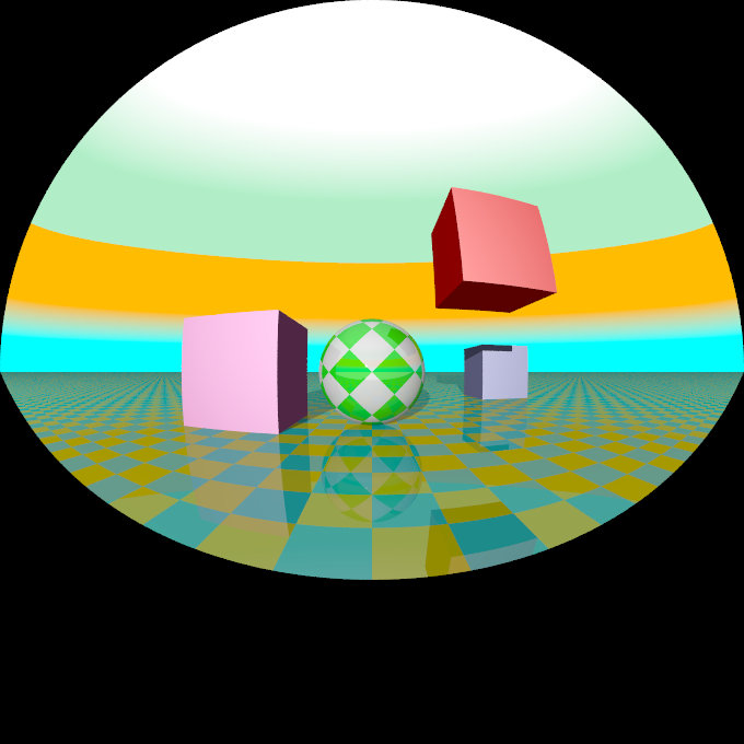
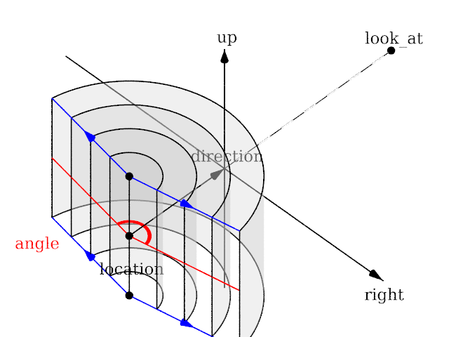
Fisheye
|
The fisheye projection |
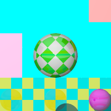
Length of direction, up and right are irrelevant. Angle is the important setting and can go up to 360.
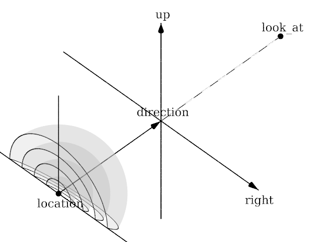
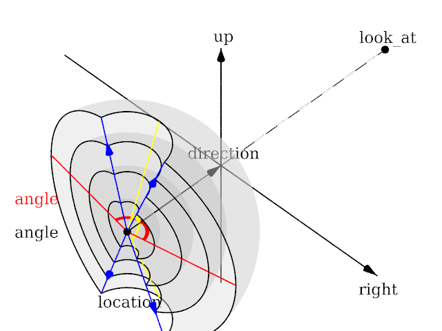
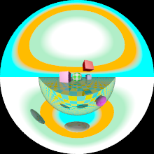
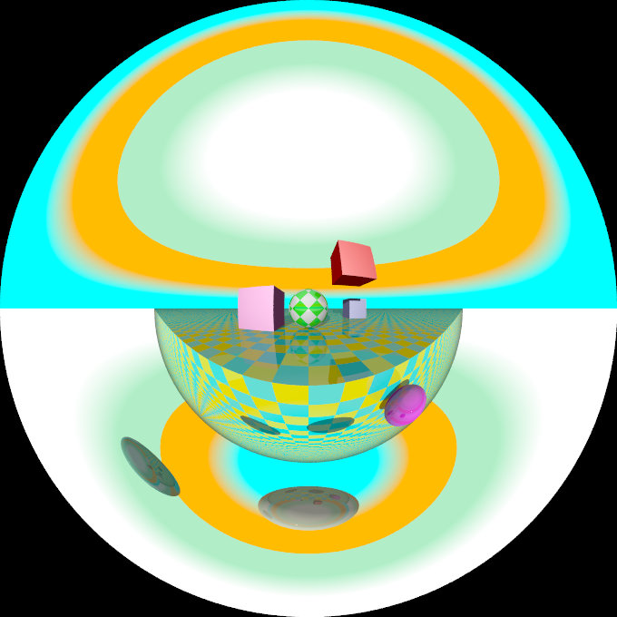
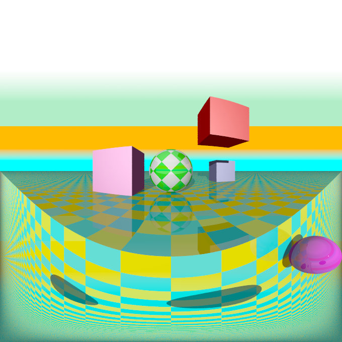
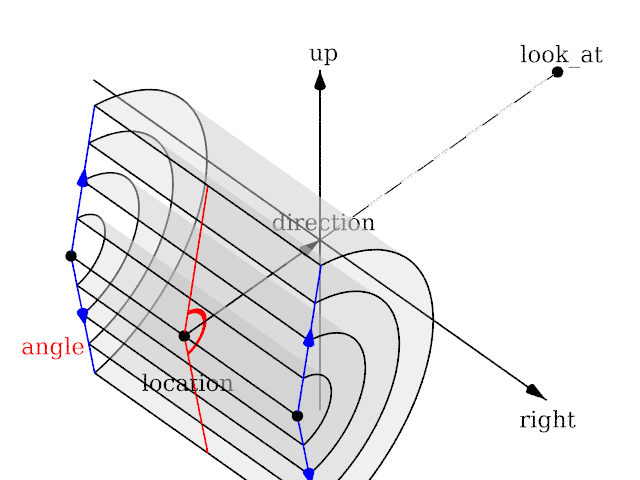
omnimax
|
The omnimax projection |
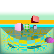
Angle is irrelevant. The relative length of up and right are important.
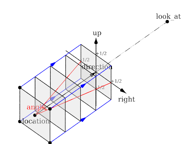
orthographic
|
The orthographic projection |
Length of direction is irrelevant unless angle is used. Lengths of up and right define the dimensions of the view. Angle can be used (as long as less than 180) and will override the length of right and up (the aspect ratio between up and right will be kept nevertheless) with a scope of a perspective camera with the same direction and angle.
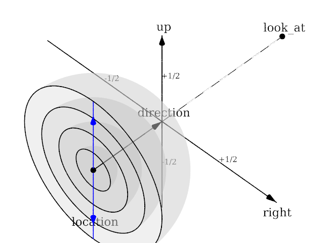
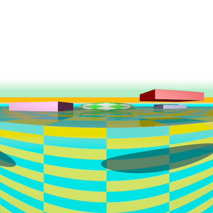
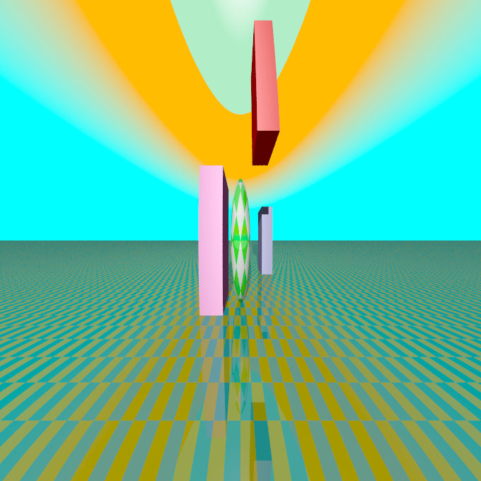
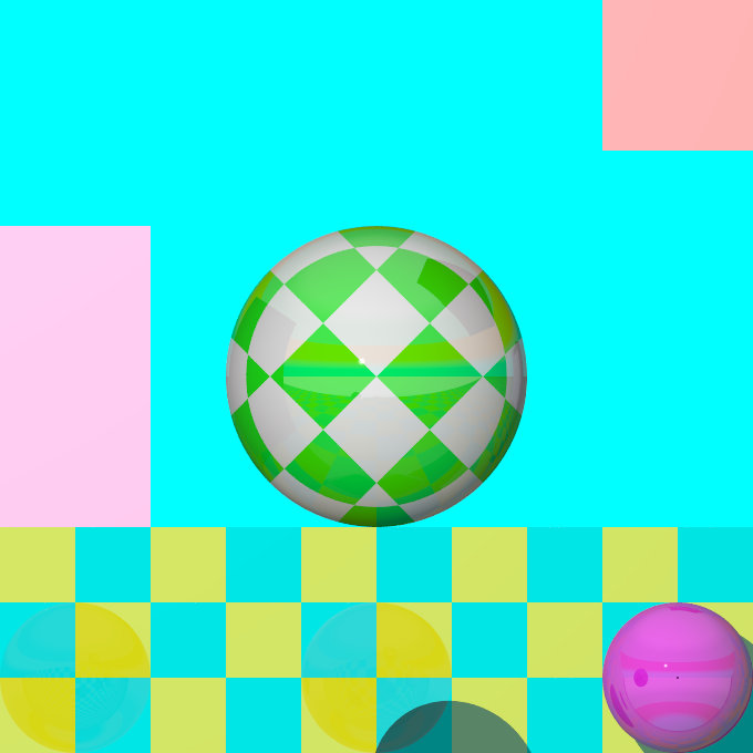
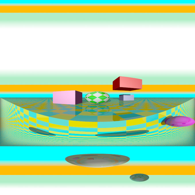
panoramic
|
The panoramic projection |
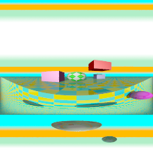
Angle is irrelevant. The relative length of direction, up and right are important as they defines the lengths of the 3 axis of the ellipsoid. With identical length and orthogonal vectors (both strongly recommended, unless used on purpose), it's identical to a spherical camera with angle 180,90.
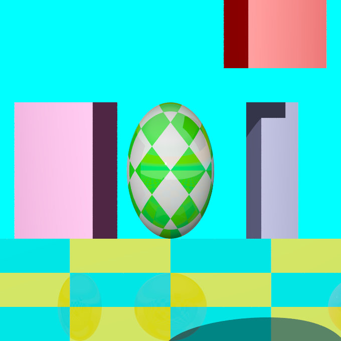
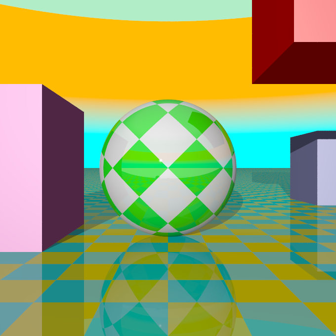
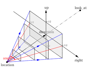
perspective
|
The perspective projection |
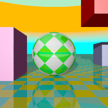
Angle can be used as long as less than 180 and will recompute the length of right and up using direction, while keeping the aspect ratio between up and right.
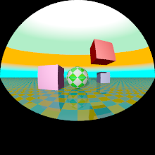
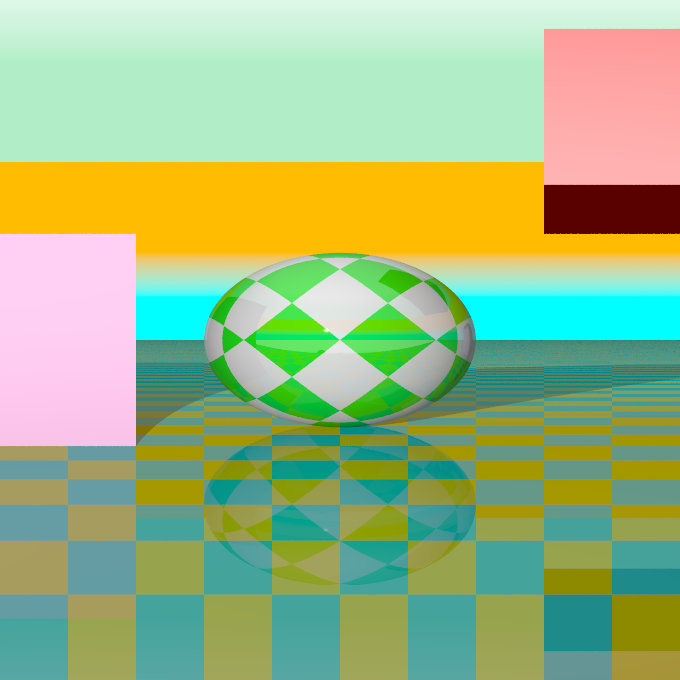
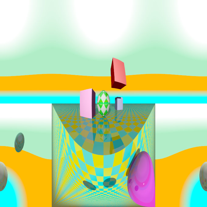
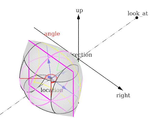
spherical
|
The spherical projection |
Lengths of direction, up and right vectors are irrelevant. Angle is the important setting, and it gets two values separated by a comma: the first is the horizontal angle, the second is the vertical angle. Both values can reach 360. If the second value is missing, it get half the value of the first.
here after some editorial changes that might need review. --Le Forgeron 09:12, 2 October 2011 (UTC)
- in section Placing the Camera (3.3.1.1)
The POV-Ray camera has ten different models,
well, it is not ten (10). If cylindrical & mesh are counted for 1 each, there is 9. perspective (1), orthographic (2), mesh(3), fisheye (4), ultra wide angle (5), omnimax(6), panoramic (7), cylindrical (8), spherical (9) (notice: I used the order and number of sub-sections) If cylindrical and mesh are counted as many (4 cylindrical, 1 or 4 mesh), it is either 12 or 15.
- in section Orthographic camera (3.3.1.2.2, end of section)
If objects are too close to the camera location they may disappear. Too close here means, behind the orthographic camera projection plane (the plane that goes through the look_at point).
It's not look_at, but location point .
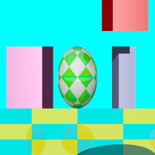
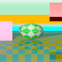
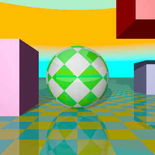
- all camera type: it would be nice to get a small sampling (i.e. an image about a fourth of the width of column, so as to have the text on the side) which illustrate each type of camera. Do we have a "typical scene" ?
- bokeh pigment would get clearer with pictures inspired from the megapov documentation.(pigment & result) (and from a strict vocabulary point, bokeh is not that kind of usage... well, should I trust wikipedia on bokeh ?)
--Le Forgeron 09:12, 2 October 2011 (UTC)
- Thanks for the follow up, the 1st two technical corrections you listed above have been done. Maybe you could expand a bit on the last two items as I'm not clear on what you are suggesting.
--jholsenback 14:27, 2 October 2011 (UTC)
I do like the layout with a small image on a side, and the paragraph on the side of the image (once demonstrated in your page). I would be delighted (as a reader), when reading about the camera, to have, inline, an example (it's a bit of lazyness, as reading the text should allow the reader to "see" the kind of view.
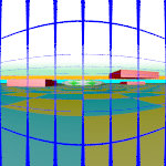
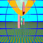
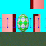
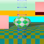
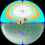
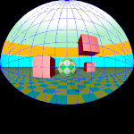
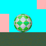
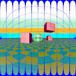
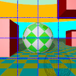
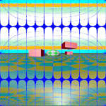
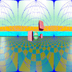 (I'm missing a mesh camera illustration... and it's probably not the best scene to show)
Regarding bokeh, I will try to use the megapov documentation to do my own illustration.
--Le Forgeron 18:56, 2 October 2011 (UTC)
- I played around with a couple scenarios and I'm not having much luck. The size of these images seems a bit small (150x150px), so they don't even really make the grade when it comes to being useful. Maybe it's my old eyes. The smallest images we have are the panels in the radiosity tutorial and they are 220px wide. Keep in mind the widest image we can use without overflowing the set page boundary is 680px. Oh and I guess you didn't notice that I had to rename ALL your first round images to conform to the naming convention. I did not rename these last ones, as somehow I think we can do just a tad better.
--jholsenback 11:11, 4 October 2011 (UTC)
For the naming convention, I hope these new pictures are more conform. (where is the relevant text ? Did I miss it ?) (I'm also always afraid to specify an existing name) Maybe a section starting with:
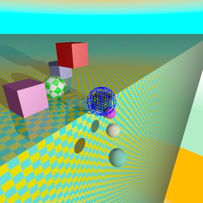 the full world, with the camera inside the grids, looking at the green and white sphere.
Then either with caption isuing :
or if big picture are better (me too, I have issue with small view)
--Le Forgeron 13:05, 9 October 2011 (UTC)
- Below is a preliminary stab at what I'm fairly sure will be close to what I'd like to use. The larger images allow for greater flexibility, as I can use a scale factor to fit the two image panel set up. View the source if you're curious about details. Much better, Don't you agree?
--jholsenback 15:33, 9 October 2011 (UTC)
- I like it. Best of both worlds: small pictures in text that can be enlarged for the details.
- I would nevertheless introduce the global view (RefImgCameraSampleScene.jpg) at the beginning of the camera section, as it might be of interest to know where the various objects are in 3D. (3 boxes & 3 spheres of different colours, two-half-infinite planes, a sphere as target and a skysphere). Do you want the code for the scene & cameras ?
--Le Forgeron 11:29, 10 October 2011 (UTC)
Perspective projection
The perspective keyword specifies the default perspective camera which simulates the classic pinhole camera. The horizontal viewing angle is either determined by the ratio between the length of the direction vector and the length of the right vector or by the optional keyword angle, which is the preferred way. The viewing angle has to be larger than 0 degrees and smaller than 180 degrees.
|
The perspective projection diagram |
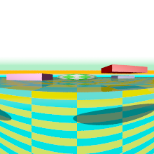
A perspective camera sample image |
Note: The angle keyword can be used as long as less than 180 degrees. It recomputes the length of right and up vectors using direction. The proper aspect ratio between the up and right vectors is maintained.
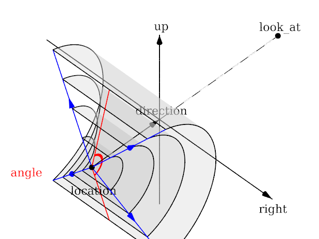
Addition of cylinder schema
--Le Forgeron 10:38, 11 October 2011 (UTC)
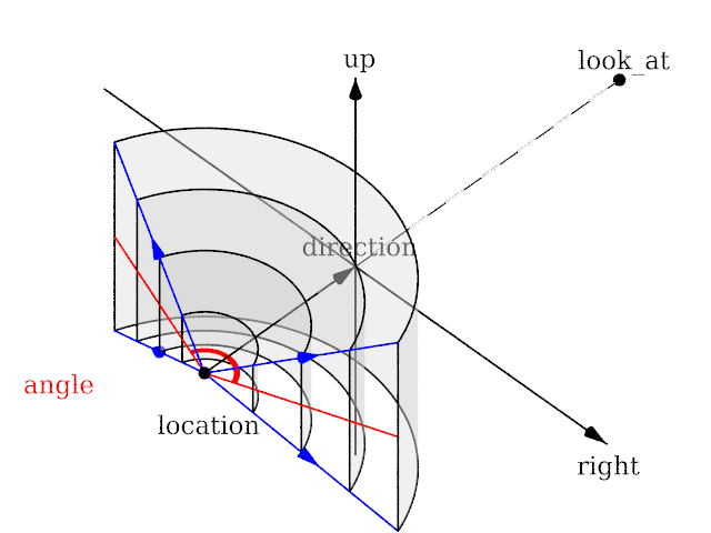
Addition of ultra wide angle schema
the aspect ratio of lengths of up/right is used to provide the vertical angle from the horizontal angle (so that the ratio of vertical angle on horizontal angle is identical to the ratio of the length of up on length of right).
when the ratio is one, a square is wrapped on a madeleine (quartic surface x²+y²+z² = x²y² +1 : the section on z=0 is a square, the sections on x=0 or y=0 are circle. sections parallel to x=0 or y=0 are ellipses)
when the ratio is not one, the bigger angle get obviously wrapped further.
When the angle reach 180, the border meet the square section.
The angle can go above 180, in which cases, when both (vertical and horizontal) angles are above 180, the parts around the corners of the square section start to be wrapped more than once.
A classical usage is using an angle of 360 but with a up/right ratio of 1/2 ("up 10*y" , "right 20*x"). it keep the top of the picture as the zenith and the bottom of the picture as the nadir, avoiding perception issues, and giving a full 360° view.
--Le Forgeron 14:02, 11 October 2011 (UTC)
