Difference between revisions of "Reference:Surface of Revolution"
Jholsenback (talk | contribs) m (1 revision: Initial Load (TF)) |
Jholsenback (talk | contribs) m (1 revision: Reference Migration Initial Load) |
(No difference)
| |
Revision as of 19:08, 15 March 2012
The sor object is a surface of revolution generated
by rotating the graph of a function about the y-axis. This function describes
the dependence of the radius from the position on the rotation axis. The
syntax is:
SOR:
  sor {
    Number_Of_Points, <Point_1>, <Point_2>, ... <Point_n>
    [ open ] [SOR_MODIFIERS...]
    }
SOR_MODIFIER:
  sturm | OBJECT_MODIFIER
SOR default values:
sturm : off
The float value Number_Of_Points specifies the
number of 2-D vectors which follow. The points
<Point_1> through <Point_n> are
two-dimensional vectors consisting of the radius and the corresponding
height, i.e. the position on the rotation axis. These points are smoothly
connected (the curve is passing through the specified points) and rotated
about the y-axis to form the SOR object. The first and last points are only
used to determine the slopes of the function at the start and end point. They
do not actually lie on the curve. The function used for the SOR object is
similar to the splines used for the lathe object. The difference is that the
SOR object is less flexible because it underlies the restrictions of any
mathematical function, i.e. to any given point y on the rotation axis belongs
at most one function value, i.e. one radius value. You cannot rotate
closed curves with the SOR object. Also, make sure that the curve does not cross zero (y-axis)
as this can result in 'less than perfect' bounding cylinders. POV-Ray will very likely fail to
render large chunks of the part of the spline contained in such an interval.
The optional keyword open allows you to remove the caps on the
SOR object. If you do this you should not use it with CSG because
the results may be wrong.
The SOR object is useful for creating bottles, vases, and things like that. A simple vase could look like this:
#declare Vase = sor {
  7,
  <0.000000, 0.000000>
  <0.118143, 0.000000>
  <0.620253, 0.540084>
  <0.210970, 0.827004>
  <0.194093, 0.962025>
  <0.286920, 1.000000>
  <0.468354, 1.033755>
  open
  }
One might ask why there is any need for a SOR object if there is already a lathe object which is much more flexible. The reason is quite simple. The intersection test with a SOR object involves solving a cubic polynomial while the test with a lathe object requires to solve a 6th order polynomial (you need a cubic spline for the same smoothness). Since most SOR and lathe objects will have several segments this will make a great difference in speed. The roots of the 3rd order polynomial will also be more accurate and easier to find.
The sturm keyword may be added to specify the slower but more
accurate Sturmian root solver. It may be used with the surface of revolution
object if the shape does not render properly.
The following explanations are for the mathematically interested reader who wants to know how the surface of revolution is calculated. Though it is not necessary to read on it might help in understanding the SOR object.
The function that is rotated about the y-axis to get the final SOR object is given by
|
Surface of Revolution Formula |
with radius r and height h.
Since this is a cubic function in h it has enough flexibility to allow smooth
curves.
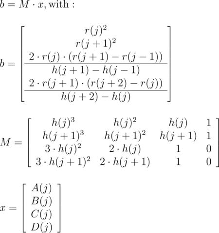
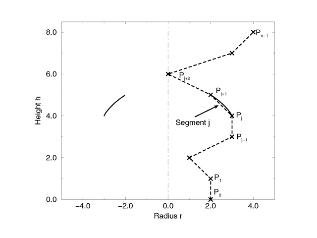
The curve itself is defined by a set of n points P(i), i=0...n-1, which are interpolated using one function for every segment of the curve. A segment j, j=1...n-3, goes from point P(j) to point P(j+1) and uses points P(j-1) and P(j+2) to determine the slopes at the endpoints. If there are n points we will have n-3 segments. This means that we need at least four points to get a proper curve. The coefficients A(j), B(j), C(j) and D(j) are calculated for every segment using the equation
|
Curve Math |
where r(j) is the radius and h(j) is the height of point P(j).
The figure below shows the configuration of the points P(i), the location of segment j, and the curve that is defined by this segment.
|
Points on a surface of revolution. |

