Difference between revisions of "Reference:Tracing Options"
Jholsenback (talk | contribs) m (1 revision: underscore link repair) |
(Indexentry fix) |
||
| Line 394: | Line 394: | ||
<code>Split_Unions=off</code>.</p> | <code>Split_Unions=off</code>.</p> | ||
| − | {{#indexentry:Options, bounding, BSP}} | + | {{#indexentry:Options, bounding, BSP|Binary Space Partitioning|BSP}} |
| − | {{#indexentry:Options, +BM1, +BM2}} | + | {{#indexentry:Options, +BM1|Options, +BM2}} |
==BSP Bounding== | ==BSP Bounding== | ||
<p>BSP (Binary Space Partitioning) tree bounding is now available. To turn it on use <code>+BM2</code> or <code>Bounding_Method=2</code> in the INI file or on the command-line. When it is in use you will get some additional statistics in the output pane regarding the built tree.</p> | <p>BSP (Binary Space Partitioning) tree bounding is now available. To turn it on use <code>+BM2</code> or <code>Bounding_Method=2</code> in the INI file or on the command-line. When it is in use you will get some additional statistics in the output pane regarding the built tree.</p> | ||
Revision as of 05:32, 11 February 2013
There is more than one way to trace a ray. Sometimes there is a trade-off between quality and speed. Sometimes options designed to make tracing faster can slow things down. This section covers options that tell POV-Ray how to trace rays with the appropriate speed and quality settings.
Symmetric MultiProcessing
Central to the many feature enhancements offered with version 3.7, POV-Ray now supports Symmetric MultiProcessing or SMP. The command line option Work_Threads=n or the +WTn switch allows you to specify the number of work threads to be used while rendering a scene. On Windows systems, the default is the number of detected cores. On Linux/Unix and OSX based systems, the default is first based on the number of detected cores, otherwise, the number of configured cores. If detection is not possible the default is set to 4. In all cases the maximum value is 512.
Render Block Size
POV-Ray provides a mechanism to specify the render block size via either an INI-style option Render_Block_Size=n or on the command-line +BSn, where n is an integer larger than or equal to 4. This represents the edge size of the square used to distribute work to the render threads, and thus the number of pixels in each block will be n squared. The default value is 32. If you specify a value that is greater than the larger of the width or height of the image being rendered, it is clipped to that value. Using render block sizes of less than eight can impact performance, particularly on large images that render quickly, as it significantly increases the amount of message traffic between the render backend and the graphical frontend, which communicate using a shared-memory queue.
Render Pattern
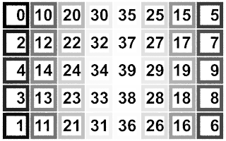
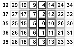
POV-Ray provides a mechanism to specify the order of render block via either an INI-style option Render_Pattern=n or on the command-line +RPn, where n is an integer between 0 and 5. This represents the various orders for the distribution of the blocks to the render threads. The default value is 0.
If you specify a value that is greater than the maximum number of patterns, it will revert to the default. Using a different Render_Pattern has only an effect on the preview of the rendered image, as the first blocks might be placed differently, but does not change the final image once the render has been completed.
|
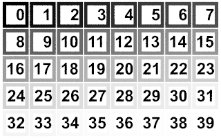
Pattern 0: is the classical order. The first block is in the top left corner, and it progress from left to right, and then it continues on the next row of blocks. Just like reading text. |
|
|
Pattern 0 |
|
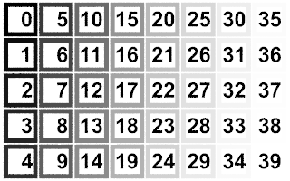
Pattern 1: is the same as pattern 0, but the rows and columns are swapped. It starts at the top left corner and it progress from top to bottom. |
|
|
Pattern 1 |
|
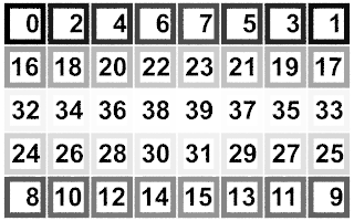
Pattern 2: The top row is processed first, starting at each corner and meeting at the center of the row, then the bottom row is processed the same way. The last block is at the very center of the image. |
|
|
Pattern 2 |
|
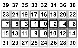
Pattern 3: Is the opposite order of pattern 2, the first block is at the center of the image, the expansion being firstly horizontal. |
|
|
Pattern 3 |
|
Pattern 4: Is the same as pattern 2, except that the rows and columns have been swapped. |
|
|
Pattern 4 |
|
Pattern 5: Is the same as pattern 3, but the rows and columns are swapped, however the expansion from the center of the image is firstly vertical. |
|
|
Pattern 5 |
Render Block Step
Whatever the chosen pattern (with +RP), the number of the next processed block can be incremented by more than 1, to jump over blocks, via either an INI-style option Render_Block_Step=n or on the command-line +RSn, where n is a positive non zero integer. The provided value of n gets reduced automatically to a smaller value if the provided value would lead to a situation where the some blocks would not get rendered.
Assuming an image made of 40 blocks, with +RS9, the order of block numbers would be:
0, 9, 18, 27, 36, 5, 14, 23, 32, 1, 10, 19, 28, 37, 6, 15, 24, 33, 2, 11, 20, 29, 38, 7, 16, 25, 34, 3, 12, 21, 30, 39, 8, 17, 26, 35, 4, 13, 22, 31.
The same 40 blocks with +RS8 would in fact use +RS7 instead. As would a +RS2 in fact be reduced to +RS1 the default.
Quality Settings
Quality=n |
Set quality value to n (0 <= n <= 11) |
+Qn |
Same as Quality=n |
The Quality=n option or +Qn
switch allows you to specify the image rendering quality. You may choose to
lower the quality for test rendering and raise it for final renders. The
quality adjustments are made by eliminating some of the calculations that are
normally performed. For example settings below 4 do not render shadows.
Settings below 8 do not use reflection or refraction. The duplicate values
allow for future expansion. The values correspond to the following quality
levels:
0, 1 |
Just show quick colors. Use full ambient lighting only. Quick colors are used only at 5 or below. |
2, 3 |
Show specified diffuse and ambient light. |
4 |
Render shadows, but no extended lights. |
5 |
Render shadows, including extended lights. |
6, 7 |
Compute texture patterns, compute photons |
8 |
Compute reflected, refracted, and transmitted rays. |
9, 10, 11 |
Compute media, radiosity and subsurface light transport. |
The default is 9 if not specified.
Automatic Bounding Control
Bounding=bool |
Turn bounding on/off |
+MB |
Turn bounding on; Set threshold to 25 or previous amount |
-MB |
Turn bounding off |
Bounding_Threshold=n |
Set bound threshold to n |
+MBn |
Turn bounding on; bound threshold to n |
-MBn |
Turn bounding off; set future threshold to n |
Light_Buffer=bool |
Turn light buffer on/off |
+UL |
Turn light buffer on |
-UL |
Turn light buffer off |
Vista_Buffer=bool |
Turn vista buffer on/off |
+UV |
Turn vista buffer on |
-UV |
Turn vista buffer off |
POV-Ray uses a variety of spatial sub-division systems to speed up
ray-object intersection tests. The primary system uses a hierarchy of nested
bounding boxes. This system compartmentalizes all finite objects in a scene
into invisible rectangular boxes that are arranged in a tree-like hierarchy.
Before testing the objects within the bounding boxes the tree is descended
and only those objects are tested whose bounds are hit by a ray. This can
greatly improve rendering speed. However for scenes with only a few objects
the overhead of using a bounding system is not worth the effort. The
Bounding=off option or -MB switch allows you to force
bounding off. The default value is on.
The Bounding_Threshold=n or
+MBn switch allows you to set the minimum number of objects
necessary before bounding is used. The default is +MB25 which
means that if your scene has fewer than 25 objects POV-Ray will automatically
turn bounding off because the overhead is not worth it. Generally it is
a good idea to use a much lower threshold like +MB5.
Additionally POV-Ray uses systems known as vista buffers and light buffers to further speed things up. These systems only work when bounding is on and when there are a sufficient number of objects to meet the bounding threshold. The vista buffer is created by projecting the bounding box hierarchy onto the screen and determining the rectangular areas that are covered by each of the elements in the hierarchy. Only those objects whose rectangles enclose a given pixel are tested by the primary viewing ray. The vista buffer can only be used with perspective and orthographic cameras because they rely on a fixed viewpoint and a reasonable projection (i. e. straight lines have to stay straight lines after the projection).
The light buffer is created by enclosing each light source in an imaginary box and projecting the bounding box hierarchy onto each of its six sides. Since this relies on a fixed light source, light buffers will not be used for area lights.
Reflected and transmitted rays do not take advantage of the light and vista buffer.
The default settings are Vista_Buffer=on or +UV
and Light_Buffer=on or +UL. The option to turn
these features off is available to demonstrate their usefulness and as
protection against unforeseen bugs which might exist in any of these bounding
systems.
In general, any finite object and many types of CSG of finite objects will properly respond to this bounding system. In addition blobs and meshes use an additional internal bounding system. These systems are not affected by the above switch. They can be switched off using the appropriate syntax in the scene file (see Blob and Mesh for details).
Text objects are split into individual letters that are bounded using the bounding box hierarchy. Some CSG combinations of finite and infinite objects are also automatically bound. The end result is that you will rarely need to add manual bounding objects as was necessary in earlier versions of POV-Ray unless you use many infinite objects.
Removing User Bounding
Remove_Bounds=bool |
Turn unnecessary bounds removal on/off |
+UR |
Turn unnecessary bounds removal on |
-UR |
Turn unnecessary bounds removal off |
Split_Unions=bool |
Turn split bounded unions on/off |
+SU |
Turn split bounded unions on |
-SU |
Turn split bounded unions off |
Early versions of POV-Ray had no system of automatic bounding or spatial
sub-division to speed up ray-object intersection tests. Users had to manually
create bounding boxes to speed up the rendering. Since version 3.0, POV-Ray
has had more sophisticated automatic bounding than any previous version. In
many cases the manual bounding on older scenes is slower than the new
automatic systems. Therefore POV-Ray removes manual bounding when it knows it
will help. In rare instances you may want to keep manual bounding. Some older
scenes incorrectly used bounding when they should have used clipping. If
POV-Ray removes the bounds in these scenes the image will not look right. To
turn off the automatic removal of manual bounds you should specify
Remove_Bounds=off or use -UR. The default is
Remove_Bounds=on.
One area where the jury is still out is the splitting of manually bounded
unions. Unbounded unions are always split into their component parts so that
automatic bounding works better. Most users do not bound unions because they
know that doing so is usually slower. If you do manually bound a union we
presume you really want it bound. For safety sake we do not presume to remove
such bounds. If you want to remove manual bounds from unions you should
specify Split_Unions=on or use +SU. The default is
Split_Unions=off.
BSP Bounding
BSP (Binary Space Partitioning) tree bounding is now available. To turn it on use +BM2 or Bounding_Method=2 in the INI file or on the command-line. When it is in use you will get some additional statistics in the output pane regarding the built tree.
Please keep in mind that this implementation of BSP is highly beta and will not speed up scenes in many cases (and in fact may slow some down). In particular the building of the tree can take a long time and lots of memory in severe cases. Using the BSP tree rather than our traditional BVH (Bounding Volume Hierarchy) system (default or +BM1) is a choice best made for specific scenes that will benefit from the way the BSP operates, and in particular if the render is long enough to offset the build time. The BSP tree build time will be constant for a given scene and set of BSP parameters, regardless of the output resolution. A 30-second BSP build may not be a good choice on a 60-second test render but may be acceptable for a 60-minute final render if the use of BSP adds a few pixels per second.
On some scenes the difference however will be dramatic, with short build times and radically increased render speed.
We have provided some BSP-related options via the INI file and encourage you to experiment with them to see if you can get better results than the default values built in to POV-Ray. We will listen to feedback from this and if necessary tweak the defaults.
Note: We do not guarantee that all of the following INI file settings will remain in the final release of 3.7
  BSP_MaxDepth=128
  BSP_BaseAccessCost=1.0
  BSP_ChildAccessCost=1.5
  BSP_IsectCost=150.0
  BSP_MissChance=0.2
The values shown above are the default. You can also get the defaults if you use a value of 0 for any of the above, or of course just by not specifying the option at all. For an explanation of what the values mean you may refer to Ray Tracing News article by Eric Haines.
See the distribution file ~scenes/bsp/Tango.pov for a good example of a scene that benefits from the BSP bounding.
Tango.pov rendered at 800x600, no AA
- With +BM1 : 70 seconds total
- With +BM2 : 48 seconds total
Anti-Aliasing Options
Antialias=bool |
Turns anti-aliasing on/off |
+A |
Turns aa on with threshold 0.3 or previous amount |
-A |
Turns anti-aliasing off |
Sampling_Method=n |
Sets aa-sampling method (only 1 or 2 are
valid) |
+AMn |
Same as Sampling_Method=n |
Antialias_Threshold=n.n |
Sets anti-aliasing threshold |
+An.n |
Sets aa on with aa-threshold at n.n |
-An.n |
Sets aa off (aa-threshold n.n in future) |
Jitter=bool |
Sets aa-jitter on/off |
+J |
Sets aa-jitter on with 1.0 or previous amount |
-J |
Sets aa-jitter off |
Jitter_Amount=n.n |
Sets aa-jitter amount to n.n. If n.n <= 0 aa-jitter is set off |
+Jn.n |
Sets aa-jitter on; jitter amount to n.n. If n.n <= 0 aa-jitter is set off |
-Jn.n |
Sets aa-jitter off (jitter amount n.n in future) |
Antialias_Depth=n |
Sets aa-depth (1 <= n <= 9) |
+Rn |
Same as Antialias_Depth=n |
Antialias_Gamma=n.n |
Sets the anti-aliasing gamma to n.n |
+AGn.n |
Same as Antialias_Gamma=n.n |
The ray-tracing process is in effect a discrete, digital sampling of the image with typically one sample per pixel. Such sampling can introduce a variety of errors. This includes a jagged, stair-step appearance in sloping or curved lines, a broken look for thin lines, moiré patterns of interference and lost detail or missing objects, which are so small they reside between adjacent pixels. The effect that is responsible for those errors is called aliasing.
Anti-aliasing is any technique used to help eliminate such errors or to reduce the negative impact they have on the image. In general, anti-aliasing makes the ray-traced image look smoother. The Antialias=on option or +A switch turns on POV-Ray's anti-aliasing system.
When anti-aliasing is turned on, POV-Ray attempts to reduce the errors by shooting more than one viewing ray into each pixel and averaging the results to determine the pixel's apparent color. This technique is called super-sampling and can improve the appearance of the final image but it drastically increases the time required to render a scene since many more calculations have to be done.
POV-Ray gives you the option to use one of two alternate super-sampling methods. The Sampling_Method=n option or +AMn switch selects either type 1 or type 2. Selecting one of those methods does not turn anti-aliasing on. This has to be done by using the +A command line switch or Antialias=on option.
Type 1 is an adaptive, non-recursive, super-sampling method. It is adaptive because not every pixel is super-sampled. Type 2 is an adaptive and recursive super-sampling method. It is recursive because the pixel is sub-divided and sub-sub-divided recursively. The adaptive nature of type 2 is the variable depth of recursion.
In the default, non-recursive method (+AM1), POV-Ray initially traces one ray per pixel. If the color of a pixel differs from its neighbors (to the left or above) by at least the set threshold value then the pixel is super-sampled by shooting a given, fixed number of additional rays. The default threshold is 0.3 but it may be changed using the Antialias_Threshold=n.n option. When the switches are used, the threshold may optionally follow the +A. For example +A0.1 turns anti-aliasing on and sets the threshold to 0.1.
The threshold comparison is computed as follows. If r1, g1, b1 and r2, g2, b2 are the rgb components of two pixels then the difference between pixels is computed by
diff = abs(r1-r2) + abs(g1-g2) + abs(b1-b2)
If this difference is greater than the threshold then both pixels are super-sampled. The rgb values are in the range from 0.0 to 1.0 thus the most two pixels can differ is 3.0. If the anti-aliasing threshold is 0.0 then every pixel is super-sampled. If the threshold is 3.0 then no anti-aliasing is done. Lower threshold means more anti-aliasing and less speed. Use anti-aliasing for your final version of a picture, not the rough draft. The lower the contrast, the lower the threshold should be. Higher contrast pictures can get away with higher tolerance values. Good values seem to be around 0.2 to 0.4.
When using the non-recursive method, the default number of super-samples is nine per pixel, located on a 3*3 grid. The
Antialias_Depth=n option or +Rn switch controls the number of rows and columns of samples taken for a super-sampled pixel. For example +R4 would give 4*4=16 samples per pixel.
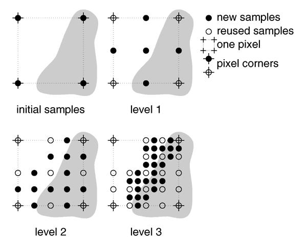
The second, adaptive, recursive super-sampling method starts by tracing four rays at the corners of each pixel. If the resulting colors differ more than the threshold amount additional samples will be taken. This is done recursively, i.e. the pixel is divided into four sub-pixels that are separately traced and tested for further subdivision. The advantage of this method is the reduced number of rays that have to be traced. Samples that are common among adjacent pixels and sub-pixels are stored and reused to avoid re-tracing of rays. The recursive character of this method makes the super-sampling concentrate on those parts of the pixel that are more likely to need super-sampling (see figure below).
|
Example of how the recursive super-sampling works. |
The maximum number of subdivisions is specified by the Antialias_Depth=n option or +Rn switch. This is different from the adaptive, non-recursive method where the total number of super-samples is specified. A maximum number of n subdivisions results in a maximum number of samples per pixel that is given by the following table. Where the first column represents anti-alias depth or +Rn option. The second column is the number of additional samples per super-sampled pixel for the non-recursive method +AM1. Lastly the third column is the maximum number of samples per super-sampled pixel for the recursive method +AM2.
1 |
1 | 9 |
2 |
4 | 25 |
3 |
9 | 81 |
4 |
16 | 289 |
5 |
25 | 1089 |
6 |
36 | 4225 |
7 |
49 | 16641 |
8 |
64 | 66049 |
9 |
81 | 263169 |
Note: The maximum number of samples in the recursive case is hardly ever reached for a given pixel. If the recursive method is used with no anti-aliasing each pixel will be the average of the rays traced at its corners. In most cases a recursion level of three is sufficient.
Another way to reduce aliasing artifacts is to introduce noise into the sampling process. This is called jittering and works because the human visual system is much more forgiving to noise than it is to regular patterns. The location of the super-samples is jittered or wiggled a tiny amount when anti-aliasing is used. Jittering is used by default but it may be turned off with the Jitter=off option or -J switch. The amount of jittering can be set with the Jitter_Amount=n.n option. When using switches the jitter scale may be specified after the +Jn.n switch. For example +J0.5 uses half the normal jitter. The default amount of 1.0 is the maximum jitter which will insure that all super-samples remain inside the original pixel.
Note: The jittering noise is random and non-repeatable so you should avoid using jitter in animation sequences as the anti-aliased pixels will vary and flicker annoyingly from frame to frame.
If anti-aliasing is not used one sample per pixel is taken regardless of the super-sampling method specified.
As the human eye is more sensitive to absolute brightness differences at a low overall brigtness than at higher ones, super-sampling based on linear light intensity differences would yield either poor anti-aliasing in darker regions, or unnecessary super-sampling in brighter regions of the image. To avoid this, POV-Ray compares gamma-adjusted values instead. (Note that this only affects the comparison operation; the averaging of the super-samples is done in whatever working color space is specified in the scene file via the assumed_gamma keyword.) The Antialias_Gamma=n.n command line option or +AGn.n sets the gamma to apply before comparison, defaulting to 2.5. Note that the value is actually the inverse of the gamma applied, in order to use the same value range as the display and file gamma settings. Neutral behavior can be achieved using Antialias_Gamma=1.0
Note: The mesh_camera feature added in version 3.7 also makes extreme super-sampling possible. See the distribution file ~scenes/camera/mesh_camera/ess/README.txt for additional information.
Radiosity Options
Radiosity High Reproducibility
As of version 3.7 a new radiosity mode has been introduced. When specifying High_Reproducibility or +HR on the command line, POV-Ray will spend extra effort to make sure renders are deterministic despite SMP (currently, radiosity is the only code to use this flag; in HR mode, radiosity pretrace starts out with fewer threads, and some extra rules are imposed on sample re-use that may cause surplus samples to be gathered).
Radiosity Load and Save
The following .ini / command line parameters are recognized:
Radiosity_File_Name="<name>"	or +RF"<name>"	to set the cache file name
Radiosity_From_File=<on/off>	or +RFI	to enable reading the radiosity file at startup
Radiosity_To_File=<on/off>	or +RFO	to enable writing new samples to the radiosity file
Note: The parameter names are preliminary, and may still be subject to change; there is a potential conflict between the shorthand forms.
If both +RFI and +RFO are specified, new samples gathered are appended; otherwise, +RFO causes the file to be overwritten if it exists.
New samples gathered are written whenever an SMP block is completed. Tests indicate that this is almost neutral regarding performance, compared to operation with radiosity file output disabled.
Radiosity Vain Pretrace
Also new as of version 3.7 an option has been added speed up radiosity pretrace:
As some computations don't contribute to the generation of radiosity samples, they can safely be skipped during radiosity pretrace to gain some speed if the pretrace's other role as a coarse preview is not required.
The following .ini file/command line options control whether pretrace performs all computations so it can double-feature as a coarse preview (vain pretrace):
Radiosity_Vain_Pretrace=bool	turns vain pretrace on/off
+RVP				turns vain pretrace on (default)
-RVP				turns vain pretrace off
Note: With vain pretrace off, preview will look remarkably odd during the radiosity pretrace phase; this is normal, and no reason to be alarmed.
At the moment, turning vain pretrace off will affect only classic lighting computations (diffuse lighting, higlights and iridescence); other features expendable during pretrace may follow in future versions.
