Difference between revisions of "Reference:Media"
Jholsenback (talk | contribs) m (1 revision: reference layout changes) |
Jholsenback (talk | contribs) m (paragraph repair) |
||
| Line 419: | Line 419: | ||
</pre> | </pre> | ||
| − | <p>In this case each media is computed independently. The resulting colors | + | <p>In this case each media is computed independently. The resulting colors are added together. Suppose one density and media returned <code>rgb<.8,.8,.4></code> and the other returned <code>rgb<.25,.25,0></code>. The resulting color is <code>rgb<1.05,1.05,.4></code>. The end result is that density areas which overlap will be especially bright and all areas will be visible. This is similar to a [[Reference:Constructive Solid Geometry|:CSG|CSG]] [[Reference:Union|:union|union]] operation.See the sample scene <code>~scenes\interior\media\media4.pov</code> for an example which illustrates this.</p> |
| − | are added together. Suppose one density and media returned <code> | ||
| − | rgb<.8,.8,.4></code> and the other returned <code> | ||
| − | rgb<.25,.25,0></code>. The resulting color is <code> | ||
| − | rgb<1.05,1.05,.4></code>. The end result is that density areas which | ||
| − | overlap will be especially bright and all areas will be visible. This is | ||
| − | similar to a [[Reference:Constructive Solid Geometry|:CSG|CSG]] [[Reference:Union|:union|union]] operation. | ||
| − | See the sample scene <code>~scenes\interior\media\media4.pov</code> for an example | ||
| − | which illustrates this.</p> | ||
Revision as of 19:19, 23 August 2012
The media statement is used to specify particulate matter
suspended in a medium such air or water. It can be used to specify smoke,
haze, fog, gas, fire, dust etc. Previous versions of POV-Ray had two
incompatible systems for generating such effects. One was halo
for effects enclosed in a transparent or semi-transparent object. The other
was atmosphere for effects that permeated the entire scene. This
duplication of systems was complex and unnecessary. Both halo
and atmosphere have been eliminated. See
Why are Interior and Media Necessary?
for further details on this change. See Object Media
for details on how to use media with objects.
See Atmospheric Media
for details on using media for atmospheric effects outside of
objects. This section and the sub-sections which follow explains the
details of the various media options which are useful for
either object media or atmospheric media.
Media works by sampling the density of particles at some specified number of
points along the ray's path. Sub-samples are also taken until the results
reach a specified confidence level. POV-Ray provides three methods of sampling.
When used in an object's interior statement, sampling only
occurs inside the object. When used for atmospheric media, the samples run from
the camera location until the ray strikes an object. Therefore for localized
effects, it is best to use an enclosing object even though the density pattern
might only produce results in a small area whether the media was enclosed or not.
The complete syntax for a media statement is as follows:
MEDIA:
  media { [MEDIA_IDENTIFIER] [MEDIA_ITEMS...] }
MEDIA_ITEMS:
  method Number | intervals Number | samples Min, Max |
  confidence Value  | variance Value | ratio Value | jitter Value
  absorption COLOR | emission COLOR | aa_threshold Value |
  aa_level Value |
  scattering {
    Type, COLOR [ eccentricity Value ] [ extinction Value ]
    }  |
  density {
    [DENSITY_IDENTIFIER] [PATTERN_TYPE] [DENSITY_MODIFIER...]
    }   |
  TRANSFORMATIONS
DENSITY_MODIFIER:
  PATTERN_MODIFIER | DENSITY_LIST | COLOR_LIST |
  color_map { COLOR_MAP_BODY } | colour_map { COLOR_MAP_BODY } |
  density_map { DENSITY_MAP_BODY }
Media default values:
aa_level     : 3
aa_threshold : 0.1
absorption   : <0,0,0>
confidence   : 0.9
emission     : <0,0,0>
intervals    : 1
jitter       : 0.0
method       : 3
ratio        : 0.9
samples      : Min 1, Max 1
variance     : 1/128
SCATTERING
COLOR        : <0,0,0>
eccentricity : 0.0
extinction   : 1.0
If a media identifier is specified, it must be the first item. All other
media items may be specified in any order. All are optional. You may have
multiple density statements in a single media
statement. See Multiple Density vs. Multiple Media
for details. Transformations apply only to the density statements which have
been already specified. Any density after a transformation is
not affected. If the media has no density
statements and none was specified in any media identifier, then the
transformation has no effect. All other media items except for
density and transformations override default values or any previously
set values for this media statement.
Note: Some media effects depend upon light sources. However the
participation of a light source depends upon the media_interaction
and media_attenuation keywords. See Atmospheric Media Interaction
and Atmospheric Attenuation for details.
Note: If you specify transmit or filter to create a transparent container object, absorption media will always cast a shadow. The same applies to scattering media unless extinction is set to zero, so if a shadow is not desired, use the no_shadow keyword for the container object. This does not apply to emission media as it never casts a shadow.
Media Types
There are three types of particle interaction in media:
absorbing, emitting, and scattering. All three activities may occur in a
single media. Each of these three specifications requires a color. Only the
red, green, and blue components of the color are used. The filter and
transmit values are ignored. For this reason it is permissible to use one
float value to specify an intensity of white color. For example, the following
two lines are legal and produce the same results:
emission 0.75
emission rgb <0.75,0.75,0.75>
Absorption
The absorption keyword specifies a color of light which is
absorbed when looking through the media. For example, absorption
rgb<0,1,0> blocks the green light but permits red and blue to
get through. Therefore a white object behind the media will appear
magenta.
The default value is rgb<0,0,0> which means no light is
absorbed -- all light passes through normally.
Emission
The emission keyword specifies the color of the light emitted from the particles. Particles which emit light are visible without requiring additional illumination. However, they will only illuminate other objects if radiosity is used with media on. This is similar to an object with high ambient values. The default value is rgb<0,0,0> which means no light is emitted.
Scattering
The syntax of a scattering statement is:
SCATTERING:
  scattering {
    Type, COLOR [ eccentricity Value ] [ extinction Value ]
    }
The first float value specifies the type of scattering. This is followed by the color of the scattered light. The default value if no scattering statement is given is rgb <0,0,0> which means no scattering occurs.
The scattering effect is only visible when light is shining on the media from a light source. This is similar to diffuse reflection off of an object. In addition to reflecting light, scattering media also absorbs light like an absorption media. The balance between how much absorption occurs for a given amount of scattering is controlled by the optional extinction keyword and a single float value. The default value of 1.0 gives an extinction effect that matches the scattering. Values such as extinction 0.25 give 25% the normal amount. Using extinction 0.0 turns it off completely. Any value other than the 1.0 default is contrary to the real physical model but decreasing extinction can give you more artistic flexibility.
The integer value Type specifies one of five different scattering phase functions representing the different models: isotropic, Mie (haze and murky atmosphere), Rayleigh, and Henyey-Greenstein.
Type 1, isotropic scattering is the simplest form of scattering because it is independent of direction. The amount of light scattered by particles in the atmosphere does not depend on the angle between the viewing direction and the incoming light.
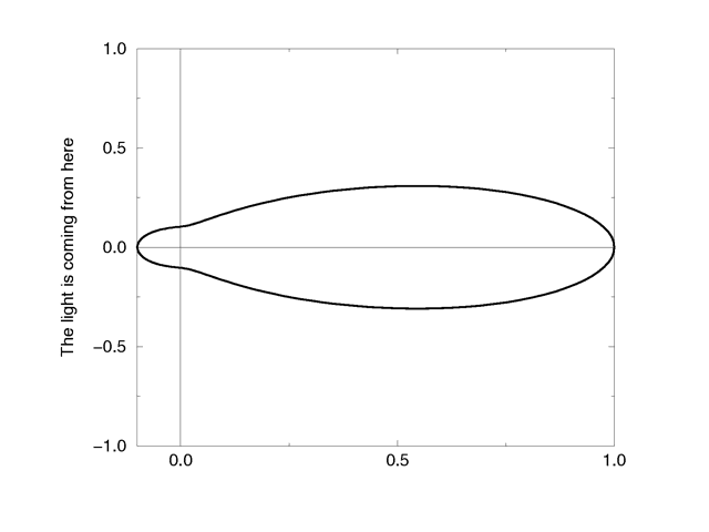
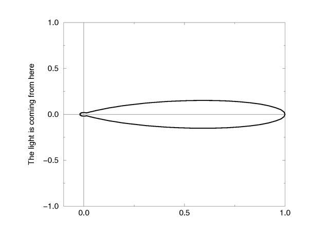
Types 2 and 3 are Mie haze and Mie murky scattering which are used for relatively small particles such as minuscule water droplets of fog, cloud particles, and particles responsible for the polluted sky. In this model the scattering is extremely directional in the forward direction, i.e. the amount of scattered light is largest when the incident light is anti-parallel to the viewing direction (the light goes directly to the viewer). It is smallest when the incident light is parallel to the viewing direction. The haze and murky atmosphere models differ in their scattering characteristics. The murky model is much more directional than the haze model.
|
The Mie haze scattering function |
|
The Mie murky scattering function |
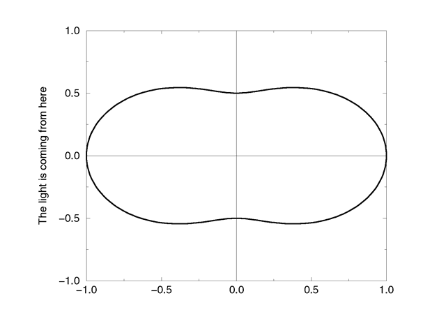
Type 4 Rayleigh scattering models the scattering for extremely small particles such as molecules of the air. The amount of scattered light depends on the incident light angle. It is largest when the incident light is parallel or anti-parallel to the viewing direction and smallest when the incident light is perpendicular to the viewing direction. You should note that the Rayleigh model used in POV-Ray does not take the dependency of scattering on the wavelength into account.
|
The Rayleigh scattering function |
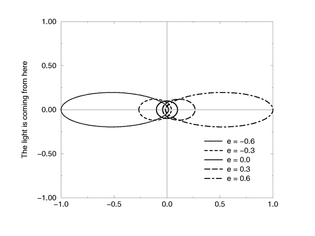
Type 5 is the Henyey-Greenstein scattering model. It is based on an analytical function and can be used to model a large variety of different scattering types. The function models an ellipse with a given eccentricity e. This eccentricity is specified by the optional keyword eccentricity which is only used for scattering type five. The default eccentricity value of zero defines isotropic scattering while positive values lead to scattering in the direction of the light and negative values lead to scattering in the opposite direction of the light. Larger values of e (or smaller values in the negative case) increase the directional property of the scattering.
|
The Henyey-Greenstein scattering function for different eccentricity values |
Note: See the section on Light Groups for additional information when using scattering media in a light group.
Sampling Parameters & Methods
Media effects are calculated by sampling the media along the path of the ray. It uses a process called Monte Carlo integration. POV-Ray provides three different types of media sampling. The method keyword lets you specify what sampling type is used.
Sample method 3 uses adaptive sampling (similar to adaptive anti-aliasing) which is very much like the sampling method used in POV-Ray 3.0 atmosphere. This code was written from the ground-up to work with media. However, adaptive sampling works by taking another sample between two existing samples if there is too much variance in the original two samples. This leads to fewer samples being taken in areas where the effect from the media remains constant. The adaptive sampling is only performed if the minimum samples are set to 3 or more.
You can specify the anti-aliasing recursion depth using the aa_level keyword followed by an integer. You can specify the anti-aliasing threshold by using the aa_threshold followed by a float. The default for aa_level is 4 and the default aa_threshold is 0.1. jitter also works with method 3.
Note: It is usually best to only use one interval with method 3. Too many intervals can lead to artifacts, and POV will create more intervals if it needs them.
Be Aware: As of version 3.5 the default sampling method is 3, and it's default for intervals is 1. Sampling methods 1 and 2 have been retained for legacy purposes.
Sample method 1 used the intervals keyword to specify the integer number of intervals used to sample the ray. For object media, the intervals are spread between the entry and exit points as the ray passes through the container object. For atmospheric media, the intervals spans the entire length of the ray from its start until it hits an object. For media types which interact with spotlights or cylinder lights, the intervals which are not illuminated by these light types are weighted differently than the illuminated intervals when distributing samples.
The ratio keyword distributes intervals differently between lit and unlit areas. The default value of ratio 0.9 means that lit intervals get more samples than unlit intervals. Note that the total number of intervals must exceed the number of illuminated intervals. If a ray passes in and out of 8 spotlights but you have only specified 5 intervals then an error occurs.
The samples Min, Max keyword specifies the minimum and maximum number of samples taken per interval. The default values are samples 1,1. The value for Max may be omitted, in which case the range Min = Max will be used.
As each interval is sampled, the variance is computed. If the variance is below a threshold value, then no more samples are needed. The variance and confidence keywords specify the permitted variance allowed and the confidence that you are within that variance. The exact calculations are quite complex and involve chi-squared tests and other statistical principles too messy to describe here. The default values are variance 1.0/128 and confidence
0.9. For slower more accurate results, decrease the variance and increase the confidence.
Note: The maximum number of samples limits the calculations even if the proper variance and confidence are never reached.
Sample method 2 distributed samples evenly along the viewing ray or light ray. The latter can make things look smoother sometimes. If you specify a maximum number of samples higher than the minimum number of samples, POV will take additional samples, but they will be random, just like in method 1. Therefore, it is suggested you set the max samples equal to the minimum samples.
jitter will cause method 2 to look similar to method 1. It should be followed by a float, and a value of 1 will stagger the samples in the full range between samples.
Density
Particles of media are normally distributed in constant density throughout
the media. However, the density statement allows you to vary the
density across space using any of POV-Ray's pattern functions such as
those used in textures. If no density statement is given then
the density remains a constant value of 1.0 throughout the media. More than
one density may be specified per media statement.
See Multiple Density vs. Multiple Media.
The syntax for density is:
DENSITY:
  density {
    [DENSITY_IDENTIFIER]
    [DENSITY_TYPE]
    [DENSITY_MODIFIER...]
    }

DENSITY_TYPE:
  PATTERN_TYPE | COLOR
  DENSITY_MODIFIER:
  PATTERN_MODIFIER | DENSITY_LIST | color_map { COLOR_MAP_BODY } |
  colour_map { COLOR_MAP_BODY } | density_map { DENSITY_MAP_BODY }
The density statement may begin with an optional density
identifier. All subsequent values modify the defaults or the values in the
identifier. The next item is a pattern type. This is any one of POV-Ray's
pattern functions such as bozo, wood, gradient, waves, etc. Of particular usefulness are the spherical,
planar, cylindrical, and boxed patterns which were previously available only for use with our discontinued
halo feature. All patterns return a value from 0.0 to 1.0. This value is interpreted as the density of the media at that particular point. See the section Pattern for details on particular pattern types. Although a solid COLOR pattern is legal, in general it is used
only when the density statement is inside a density_map.
General Density Modifiers
A density statement may be modified by any of the general pattern modifiers such as transformations, turbulence and warp. See Pattern Modifiers for details. In addition, there are several density-specific modifiers which can be used.
Density with color_map
Typically, a media uses just one constant color throughout.
Even if you vary the density, it is usually just one color which is specified
by the absorption, emission, or
scattering keywords. However, when using emission to
simulate fire or explosions, the center of the flame (high density area) is
typically brighter and white or yellow. The outer edge of the flame (less
density) fades to orange, red, or in some cases deep blue. To model the
density-dependent change in color which is visible, you may specify a
color_map. The pattern function returns a value from 0.0 to 1.0 and
the value is passed to the color map to compute what color or blend of colors
is used. See Color Maps for details on how pattern values work
with color_map. This resulting color is multiplied by the
absorption, emission and scattering color.
Currently there is no way to specify different color maps for each media type
within the same media statement.
Consider this example:
media {
  emission 0.75
  scattering {1, 0.5}
  density {
    spherical
    color_map {
      [0.0 rgb <0,0,0.5>]
      [0.5 rgb <0.8, 0.8, 0.4>]
      [1.0 rgb <1,1,1>]
      }
    }
  }
The color map ranges from white at density 1.0 to bright yellow at density 0.5 to deep blue at density 0. Assume we sample a point at density 0.5. The emission is 0.75*<0.8,0.8,0.4> or <0.6,0.6,0.3>. Similarly the scattering color is 0.5*<0.8,0.8,0.4> or <0.4,0.4,0.2>.
For block pattern types checker, hexagon, and
brick you may specify a color list such as this:
density {
 checker
   density {rgb<1,0,0>}
   density {rgb<0,0,0>}
   }
See Color List Pigments
which describes how pigment uses a color list. The same principles
apply when using them with density.
Density Maps and Density Lists
In addition to specifying blended colors with a color map you may create a
blend of densities using a density_map. The syntax for a density
map is identical to a color map except you specify a density in each map
entry (and not a color).
The syntax for density_map is as follows:
DENSITY_MAP:
  density_map { DENSITY_MAP_BODY }
DENSITY_MAP_BODY:
  DENSITY_MAP_IDENTIFIER | DENSITY_MAP_ENTRY...
DENSITY_MAP_ENTRY:
  [ Value DENSITY_BODY ]
Where Value is a float value between 0.0 and 1.0
inclusive and each DENSITY_BODY is anything which can be inside a
density{...} statement. The density keyword and
{} braces need not be specified.
Note: The [] brackets are part of the actual
DENSITY_MAP_ENTRY. They are not notational symbols denoting optional
parts. The brackets surround each entry in the density map.
There may be from 2 to 256 entries in the map.
Density maps may be nested to any level of complexity you desire. The densities in a map may have color maps or density maps or any type of density you want.
Entire densities may also be used with the block patterns such as checker, hexagon and brick. For example:
density {
  checker
    density { Flame scale .8 }
    density { Fire scale .5 }
    }
Note: In the case of block patterns the density wrapping
is required around the density information.
A density map is also used with the average density type. See
Average for details.
You may declare and use density map identifiers but the only way to declare a density block pattern list is to declare a density identifier for the entire density.
Multiple Density vs. Multiple Media
It is possible to have more than one media specified per
object and it is legal to have more than one density per
media. The effects are quite different. Consider this example:
object {
  MyObject
  pigment { rgbf 1 }
  interior {
    media {
      density { Some_Density }
      density { Another_Density }
      }
    }
  }
As the media is sampled, calculations are performed for each density
pattern at each sample point. The resulting samples are multiplied together.
Suppose one density returned rgb<.8,.8,.4> and the other
returned rgb<.25,.25,0>. The resulting color is
rgb<.2,.2,0>.
Note: In areas where one density returns zero, it will wipe out the other density. The end result is that only density areas which overlap will be visible. This is similar to a CSG intersection operation. Now consider
object {
  MyObject
  pigment { rgbf 1 }
  interior {
    media {
      density { Some_Density }
      }
    media {
      density { Another_Density }
      }
    }
  }
In this case each media is computed independently. The resulting colors are added together. Suppose one density and media returned rgb<.8,.8,.4> and the other returned rgb<.25,.25,0>. The resulting color is rgb<1.05,1.05,.4>. The end result is that density areas which overlap will be especially bright and all areas will be visible. This is similar to a CSG union operation.See the sample scene ~scenes\interior\media\media4.pov for an example which illustrates this.


