Reference:Camera
The camera definition describes the position, projection type and properties of the camera viewing the scene. Its syntax is:
CAMERA:
  camera{ [CAMERA_ITEMS...] }
CAMERA_ITEMS:
  CAMERA_TYPE | CAMERA_VECTOR | CAMERA_MODIFIER |
  CAMERA_IDENTIFIER
CAMERA_TYPE:
  perspective | orthographic | mesh_camera { MESHCAM_MODIFIERS } | fisheye | ultra_wide_angle |
  omnimax | panoramic | cylinder CylinderType | spherical | user_defined { USER_DEFINED_MODIFIERS }
CAMERA_VECTOR:
  location <Location> | right <Right> | up <Up> |
  direction <Direction> | sky <Sky>
CAMERA_MODIFIER:
  angle HORIZONTAL [VERTICAL] | look_at <Look_At> |
  blur_samples [MIN_SAMPLES,] MAX_SAMPLES | aperture Size |
  focal_point <Point> | confidence Blur_Confidence |
  variance Blur_Variance | [bokeh { pigment { BOKEH }}] |
  NORMAL | TRANSFORMATION | [MESHCAM_SMOOTH]
MESHCAM_MODIFIERS:
  rays per pixel & distribution type & [max distance] & MESH_OBJECT & [MESH_OBJECT...]
BOKEH:
  a COLOR_VECTOR in the range of <0,0,0> ... <1,1,0>
MESHCAM_SMOOTH:
  smooth
USER_DEFINED_MODIFIERS:
  [location  <function{}>, <function{}>, <function{}>]
  [direction <function{}>, <function{}>, <function{}>]
Camera default values:
DEFAULT CAMERA:
camera {
  perspective
  location <0,0,0>
  direction <0,0,1>
  right 1.33*x
  up y
  sky <0,1,0>
  }

CAMERA TYPE: perspective
  angle      : ~67.380 ( direction_length=0.5*
             right_length/tan(angle/2) )
  confidence : 0.9 (90%)
  direction  : <0,0,1>
  focal_point: <0,0,0>
  location   : <0,0,0>
  look_at    : z
  right      : 1.33*x
  sky        : <0,1,0>
  up         : y
  variance   : 1/128
Depending on the projection type zero or more of the parameters are required:
- If no camera is specified the default camera is used.
- If no projection type is given the perspective camera will be used (pinhole camera).
- The CAMERA_TYPE has to be the first item in the camera statement.
- Other CAMERA_ITEMs may legally appear in any order.
- For other than the perspective camera, the minimum that has to be specified is the CAMERA_TYPE, the cylindrical camera also requires the CAMERA_TYPE to be followed by a float.
- The Orthographic camera has two 'modes'. For the pure orthographic projection up or right have to be specified. For an orthographic camera, with the same area of view as a perspective camera at the plane which goes through the look_at point, the angle keyword has to be use. A value for the angle is optional.
- All other CAMERA_ITEMs are taken from the default camera, unless they are specified differently.
Placing the Camera
The POV-Ray camera has 9 different models and they are as follows:
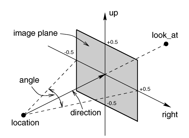
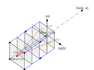
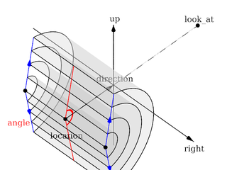
Each of which uses a different projection method to project the scene onto your screen. Regardless of the projection type all cameras use location, right, up, direction, and other keywords to determine the location and orientation of the camera. The type keywords and these four vectors fully define the camera. All other camera modifiers adjust how the camera does its job. The meaning of these vectors and other modifiers differ with the projection type used. A more detailed explanation of the camera types follows later. In the sub-sections which follows, we explain how to place and orient the camera by the use of these four vectors and the sky and look_at modifiers. You may wish to refer to the illustration of the perspective camera below as you read about these
vectors.
|
Basic (default) camera geometry |
Location and Look_At
Under many circumstances just two vectors in the camera statement are all
you need to position the camera: location and look_at
vectors. For example:
camera {
  location <3,5,-10>
  look_at <0,2,1>
  }
The location is simply the x, y, z coordinates of the camera. The camera
can be located anywhere in the ray-tracing universe. The default location is
<0,0,0>. The look_at vector tells POV-Ray to
pan and tilt the camera until it is looking at the specified x, y, z
coordinates. By default the camera looks at a point one unit in the
z-direction from the location.
The look_at modifier should almost always be the last item in
the camera statement. If other camera items are placed after the
look_at vector then the camera may not continue to look at the
specified point.
The Sky Vector
Normally POV-Ray pans left or right by rotating about the y-axis until it
lines up with the look_at point and then tilts straight up or
down until the point is met exactly. However you may want to slant the camera
sideways like an airplane making a banked turn. You may change the tilt of
the camera using the sky vector. For example:
camera {
  location <3,5,-10>
  sky   <1,1,0>
  look_at <0,2,1>
  }
This tells POV-Ray to roll the camera until the top of the camera is in
line with the sky vector. Imagine that the sky vector is an antenna pointing
out of the top of the camera. Then it uses the sky vector as the
axis of rotation left or right and then to tilt up or down in line with the
sky until pointing at the look_at point. In effect
you are telling POV-Ray to assume that the sky isn't straight up.
The sky vector does nothing on its own. It only modifies the
way the look_at vector turns the camera. The default value is
sky<0,1,0>.
Angles
The angle keyword followed by a float expression specifies
the (horizontal) viewing angle in degrees of the camera used. Even though it
is possible to use the direction vector to determine the viewing
angle for the perspective camera it is much easier to use the
angle keyword.
When you specify the angle, POV-Ray adjusts the length of the
direction vector accordingly. The formula used is
direction_length = 0.5 * right_length / tan(angle / 2) where
right_length is the length of the right vector. You should
therefore specify the direction and right vectors
before the angle keyword. The right vector is
explained in the next section.
There is no limitation to the viewing angle except for the perspective projection. If you choose viewing angles larger than 360 degrees you will see repeated images of the scene (the way the repetition takes place depends on the camera). This might be useful for special effects.
The spherical camera has the option to also specify a vertical
angle. If not specified it defaults to the horizontal angle/2
For example if you render an image with a 2:1 aspect ratio and map it to a sphere using spherical mapping, it will recreate the scene. Another use is to map it onto an object and if you specify transformations for the object before the texture, say in an animation, it will look like reflections of the environment (sometimes called environment mapping).
The Direction Vector
You will probably not need to explicitly specify or change the camera
direction vector but it is described here in case you do. It
tells POV-Ray the initial direction to point the camera before moving it with
the look_at or rotate vectors (the default value is
direction<0,0,1>). It may also be used to control the
(horizontal) field of view with some types of projection. The length of the
vector determines the distance of the viewing plane from the camera's
location. A shorter direction vector gives a wider view while a
longer vector zooms in for close-ups. In early versions of POV-Ray, this was
the only way to adjust field of view. However zooming should now be done
using the easier to use angle keyword.
If you are using the ultra_wide_angle, panoramic,
or cylindrical projection you should use a unit length
direction vector to avoid strange results. The length of the
direction vector does not matter when using the
orthographic, fisheye, or omnimax projection
types.
Up and Right Vectors
The primary purpose of the up and right vectors
is to tell POV-Ray the relative height and width of the view screen. The
default values are:
right 4/3*x
up y
In the default perspective camera, these two vectors also
define the initial plane of the view screen before moving it with the
look_at or rotate vectors. The length of the
right vector (together with the direction vector) may
also be used to control the (horizontal) field of view with some types of
projection. The look_at modifier changes both the up
and right vectors. The angle calculation depends on the
right vector.
Most camera types treat the up and right vectors
the same as the perspective type. However several make special
use of them. In the orthographic projection: The lengths of the
up and right vectors set the size of the viewing
window regardless of the direction vector length, which is not
used by the orthographic camera.
When using cylindrical projection: types 1 and 3, the axis of
the cylinder lies along the up vector and the width is
determined by the length of right vector or it may be overridden
with the angle vector. In type 3 the up vector
determines how many units high the image is. For example if you have up
4*y on a camera at the origin. Only points from y=2 to y=-2 are
visible. All viewing rays are perpendicular to the y-axis. For type 2 and 4,
the cylinder lies along the right vector. Viewing rays for type
4 are perpendicular to the right vector.
Note: The up, right, and direction vectors should always remain perpendicular to each other or the image will be distorted. If this is not the case a warning message will be printed. The vista buffer will not work for non-perpendicular camera vectors.
Aspect Ratio
Together the up and right vectors define the
aspect ratio (height to width ratio) of the resulting image. The
default values up<0,1,0> and
right<1.33,0,0> result in an aspect ratio of 4 to 3. This is the
aspect ratio of a typical computer monitor. If you wanted a tall skinny image
or a short wide panoramic image or a perfectly square image you should adjust
the up and right vectors to the appropriate
proportions.
Most computer video modes and graphics printers use perfectly square pixels.
For example Macintosh displays and IBM SVGA modes 640x480, 800x600 and
1024x768 all use square pixels. When your intended viewing method uses square
pixels then the width and height you set with the Width and
Height options or +W or +H switches
should also have the same ratio as the up and right
vectors.
Note: 640/480 = 4/3 so the ratio is proper for this square pixel mode.
Not all display modes use square pixels however. For example IBM VGA mode
320x200 and Amiga 320x400 modes do not use square pixels. These two modes
still produce a 4/3 aspect ratio image. Therefore images intended to be
viewed on such hardware should still use 4/3 ratio on their up
and right vectors but the pixel settings will not be 4/3.
For example:
camera {
  location <3,5,-10>
  up    <0,1,0>
  right  <1,0,0>
  look_at <0,2,1>
  }
This specifies a perfectly square image. On a square pixel display like
SVGA you would use pixel settings such as +W480 +H480 or
+W600 +H600. However on the non-square pixel Amiga 320x400 mode you
would want to use values of +W240 +H400 to render a square
image.
The bottom line issue is this: the up and right
vectors should specify the artist's intended aspect ratio for the image
and the pixel settings should be adjusted to that same ratio for square
pixels and to an adjusted pixel resolution for non-square pixels. The
up and right vectors should not be adjusted
based on non-square pixels.
Handedness
The right vector also describes the direction to the right of
the camera. It tells POV-Ray where the right side of your screen is. The sign
of the right vector can be used to determine the handedness of
the coordinate system in use. The default value is:
right<1.33,0,0>. This means that the +x-direction is to the
right. It is called a left-handed system because you can use your
left hand to keep track of the axes. Hold out your left hand with your palm
facing to your right. Stick your thumb up. Point straight ahead with your
index finger. Point your other fingers to the right. Your bent fingers are
pointing to the +x-direction. Your thumb now points into +y-direction. Your
index finger points into the +z-direction.
To use a right-handed coordinate system, as is popular in some CAD programs
and other ray-tracers, make the same shape using your right hand. Your thumb
still points up in the +y-direction and your index finger still points
forward in the +z-direction but your other fingers now say the +x-direction
is to the left. That means that the right side of your screen is now in the
-x-direction. To tell POV-Ray to act like this you can use a negative x value
in the right vector such as:
right<-1.33,0,0>. Since having x values increasing to the left
does not make much sense on a 2D screen you now rotate the whole thing 180
degrees around by using a positive z value in your camera's location. You
end up with something like this.
camera {
  location <0,0,10>
  up    <0,1,0>
  right  <-1.33,0,0>
  look_at <0,0,0>
  }
Now when you do your ray-tracer's aerobics, as explained in the section Understanding POV-Ray's Coordinate System, you use your right hand to determine the direction of rotations.
In a two dimensional grid, x is always to the right and y is up. The two versions of handedness arise from the question of whether z points into the screen or out of it and which axis in your computer model relates to up in the real world.
Architectural CAD systems, like AutoCAD, tend to use the God's Eye orientation that the z-axis is the elevation and is the model's up direction. This approach makes sense if you are an architect looking at a building blueprint on a computer screen. z means up, and it increases towards you, with x and y still across and up the screen. This is the basic right handed system.
Stand alone rendering systems, like POV-Ray, tend to consider you as a participant. You are looking at the screen as if you were a photographer standing in the scene. The up direction in the model is now y, the same as up in the real world and x is still to the right, so z must be depth, which increases away from you into the screen. This is the basic left handed system.
Transforming the Camera
The various transformations such as translate and
rotate modifiers can re-position the camera once you have defined
it. For example:
camera {
  location < 0, 0, 0>
  direction < 0, 0, 1>
  up    < 0, 1, 0>
  right   < 1, 0, 0>
  rotate  <30, 60, 30>
  translate < 5, 3, 4>
  }
In this example, the camera is created, then rotated by 30 degrees about the x-axis, 60 degrees about the y-axis and 30 degrees about the z-axis, then translated to another point in space.
Types of Projection
|
The following sections explain the different projection types that can be used with the scene camera. The most common types are the perspective and orthographic projections. The CAMERA_TYPE should be the first item in a |
|
|
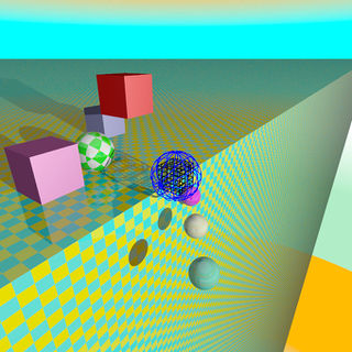
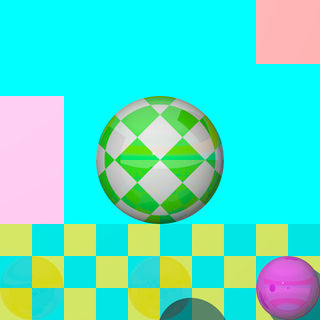
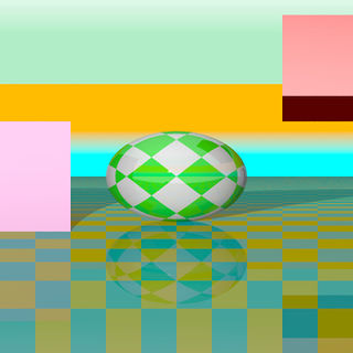
The camera sample scene global view |
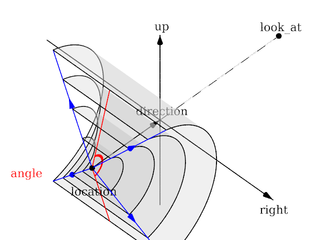
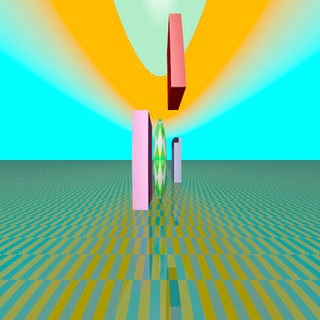
Note: The vista buffer feature can only be used with the perspective and orthographic camera.
Perspective projection
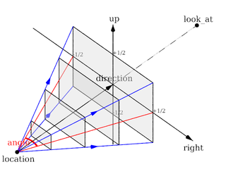
The perspective keyword specifies the default perspective camera which simulates the classic pinhole camera. The horizontal viewing angle is either determined by the ratio between the length of the direction vector and the length of the right vector or by the optional keyword angle, which is the preferred way. The viewing angle has to be larger than 0 degrees and smaller than 180 degrees.
|
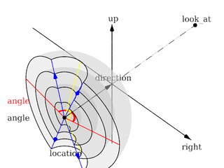
The perspective projection diagram |
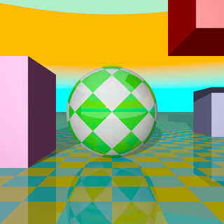
A perspective camera sample image |
Note: The angle keyword can be used as long as less than 180 degrees. It recomputes the length of right and up vectors using direction. The proper aspect ratio between the up and right vectors is maintained.
Orthographic projection
The orthographic camera offers two modes of operation:
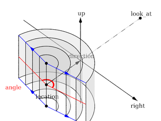
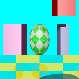
The pure orthographic projection. This projection uses parallel camera rays to create an image of the scene. The area of view is determined by the lengths of the right and up vectors. One of these has to be specified, they are not taken from the default camera. If omitted the second method of the camera is used.
If, in a perspective camera, you replace the perspective keyword by orthographic and leave all other parameters the same, you will get an orthographic view with the same image area, i.e. the size of the image is
the same. The same can be achieved by adding the angle keyword to an orthographic camera. A value for the angle is optional. So this second mode is active if no up and right are within the camera statement, or when the angle keyword is within the camera statement.
You should be aware though that the visible parts of the scene change when switching from perspective to orthographic view. As long as all objects of interest are near the look_at point they will be still visible if the orthographic camera is used. Objects farther away may get out of view while nearer objects will stay in view.
If objects are too close to the camera location they may disappear. Too close here means, behind the orthographic camera projection plane (the plane that goes through the location point).
|
The orthographic projection diagram |
An orthographic camera sample image |
Note: The length of direction is irrelevant unless angle is used. The lengths of up and right define the dimensions of the view. The angle keyword can be used, as long as less than 180. It will override the length of the right and up vectors (the aspect ratio between up and right will be kept nevertheless) with a scope of a perspective camera having the same direction and angle.
Mesh projection
The mesh projection is a special camera type that allows complete control of the ray origin and direction for each pixel of the output image. The basic concept is to associate pixels with faces defined within a previously declared mesh or mesh2 object. The MESH_OBJECT_IDENTIFIER need not be instantiated in the scene, though it can be, and doing so can lead to some interesting uses, such as texture baking or illumination calculations.
In its simplest form, each pixel of the output image is assigned to a face of the mesh according to (width * (int) y) + (int) x, however, more complex mapping is possible via multiple meshes and multiple rays per pixel. The type of mapping in use is determined by the distribution type parameter in the camera declaration. Except for mapping #3, the ray origin will be set to the centroid of the face, and the direction will be that of the face's normal. For mapping #3, barycentric co-ordinates are determined from the UV co-ordinates of the first face to match the X and Y position, and those are then converted to a position on the face which will serve as the ray origin. Support is provided to move the origin off the face along the normal, and to reverse the ray direction.
For most of the distribution methods, any POV feature that causes sub-pixel positioning to be used for shooting rays (e.g. anti-aliasing or jitter) will not do anything useful, because X and Y are converted to integers for indexing purposes. At this time, no warning is issued if anti-aliasing or jitter is requested when rendering a non-applicable distribution; this may be added later.
The syntax for the mesh camera is as follows:
camera {
  mesh_camera {
    rays per pixel
    distribution type
    [max distance]
    mesh {
      MESH_OBJECT_IDENTIFIER
      [TRANSFORMATIONS]
    }
    [mesh ...]
  }
  [location]
  [direction]
  [smooth]
  }
Note: The mesh camera is an experimental feature introduced in version 3.7 beta 39 and its syntax is likely to change. Additionally, many of the normal camera concepts presented in this section (such as location and direction) either do not work as they do for other cameras or do not work at all (for example, the concept of 'up' simply does not apply to a mesh camera). It should also be kept in mind that the camera has not yet been tested with many of POV-Ray's advanced features such as photons and radiosity, and more work in that area is likely to be needed.
Rays Per Pixel
This float parameter controls the number of rays that will be shot for each pixel in the output image. Each distribution allows different values, but the minimum is always 1.
Distribution Type
This float parameter controls how pixels are assigned to faces as documented below:
- distribution #0
This method allows single or multiple rays per pixel, with the ray number for that pixel allocated to each mesh in turn. The index into the meshes is the ray number, where rays per pixel is greater than one, and the index into the selected mesh is the pixel number within the output image. If there is no face at that pixel position, the resulting output pixel is unaffected.
You must supply at least as many meshes as rays per pixel. Each pixel is shot rays per pixel times, and the results averaged. Any ray that does not correspond with a face (i.e. the pixel number is greater than or equal to the face count) does not affect the resulting pixel color. Generally, it would be expected that the number of faces in each mesh is the same, but this is not a requirement. Keep in mind that a ray that is not associated with a face is not the same thing as a ray that is but that, when shot, hits nothing. The latter will return a pixel (even if it is transparent or the background color), whereas the former causes the ray to not be shot in the first place; hence, it is not included in the calculation of the average for the pixel.
Using multiple rays per pixel is useful for generating anti-aliasing (since standard AA won't work) or for special effects such as focal blur, motion blur, and so forth, with each additional mesh specified in the camera representing a slightly different camera position.
Note: It is legal to use transformations on meshes specified in the camera body, hence it's possible to obtain basic anti-aliasing by using a single mesh multiple times, with subsequent ones jittered slightly from the first combined with a suitable rays per pixel count.
- distribution #1
This method allows both multiple rays per pixel and summing of meshes, in other words the faces of all the supplied meshes are logically summed together as if they were one single mesh. In this mode, if you specify more than one ray per pixel, the second ray for a given pixel will go to the face at (width * height * ray_number) + pixel_number, where ray_number is the count of rays shot into a specific pixel. If the calculated face index exceeds the total number of faces for all the meshes, no ray is shot.
The primary use for this summing method is convenience in generation of the meshes, as some modelers slow down to an irritating extent with very large meshes. Using distribution #1 allows these to be split up.
- distribution #2
Distribution method 2 is a horizontal array of sub-cameras, one per mesh (i.e. like method #0, it does not sum meshes). The image is divided horizontally into #num_meshes blocks, with the first mesh listed being the left-most camera, and the last being the right-most. The most obvious use of this would be with two meshes to generate a stereo camera arrangement.
In this mode, you can (currently) only have a single ray per pixel.
- distribution #3
This method will reverse-map the face from the UV co-ordinates. Currently, only a single ray per pixel is supported, however, unlike the preceding methods, standard AA and jitter will work. This method is particularly useful for texture baking and resolution-independent mesh cameras, but requires that the mesh have a UV map supplied with it.
You can use the smooth modifier to allow interpolation of the normals at the vertices. This allows for use of UV mapped meshes as cameras with the benefit of not being resolution dependent, unlike the other distributions. The interpolation is identical to that used for smooth_triangles.
If used for texture baking, the generated image may have visible seams when applied back to the mesh, this can be mitigated. Also, depending on the way the original UV map was set up, using AA may produce incorrect pixels on the outside edge of the generated maps.
Max Distance
This is an optional floating-point value which, if greater than EPSILON (a very small value used internally for comparisons with 0), will be used as the limit for the length of any rays cast. Objects at a distance greater than this from the ray origin will not be intersected by the ray.
The primary use for this parameter is to allow a mesh camera to 'probe' a scene in order to determine whether or not a given location contains a visible object. Two examples would be a camera that divides the scene into slices for use in 3d printing or to generate an STL file, and a camera that divides the scene into cubes to generate voxel information. In both cases, some external means of processing the generated image into a useful form would be required.
It should be kept in mind that this method of determining spatial information is not guaranteed to generate an accurate result, as it is entirely possible for a ray to miss an object that is within its section of the scene, should that object have features that are smaller than the resolution of the mesh being used. In other words, it is (literally) hit and miss. This issue is conceptually similar to aliasing in a normal render.
It is left as an exercise for the reader to come up with means of generating pixel information that carries useful information, given the lack of light sources within the interior of an opaque object (hint: try ambient).
Mesh Object
One or more mesh or mesh2 objects to be used for the camera. These will be treated differently depending on the distribution method, as explained above. Transformations on the meshes can be used here, and will reflect on the resulting image as it would be expected for a regular camera.
About the Location Vector
With this special camera, location doesn't affect where the camera is placed per se (that information is on the mesh object itself), but is used to move the origin of the ray off the face, along the normal of that face. This would typically be done for texture baking or illumination calculation scenes where the camera mesh is also instantiated into the scene, usually only a tiny amount of displacement is needed. The X and Y for location is not currently used, and the Z always refers to the normal of the face, rather than the real Z direction in the scene.
About the Direction Vector
Like location, this doesn't correspond to the real direction vector of the camera. It serves only to reverse the normal of all the faces, if necessary. If the Z component is less than -EPSILON, then the rays will be shot in the opposite direction than they would otherwise have been. X and Y are not used.
The Smooth Modifier
This optional parameter is only useful with distribution #3, and will cause the ray direction to be interpolated according to the same rules as are applied to smooth triangles. For this to work, the mesh must have provided a normal for each vertex.
Note: See the sample scene files located in ~scenes/camera/mesh_camera/ for additional usages and other samples of mesh cameras. There are also some useful macros to assist in generating and processing meshes for use as cameras.
Fisheye projection
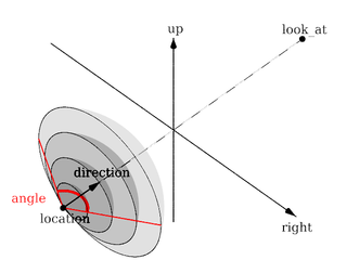
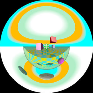
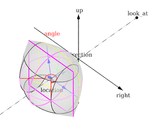
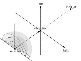
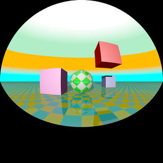
This is a spherical projection. The viewing angle is specified by the angle keyword. An angle of 180 degrees creates the "standard" fisheye while an angle of 360 degrees creates a super-fisheye or "I-see-everything-view". If you use this projection you should get a circular image. If this is not the case, i.e. you get an elliptical image, you should read Aspect Ratio.
|
The fisheye projection diagram |
A fisheye camera sample image |
Note: The length of the direction, up and right vectors are irrelevant. The angle keyword is the important setting.
Ultra wide angle projection
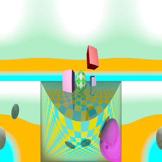
The ultra wide angle projection is somewhat similar to the fisheye, but it projects the image onto a rectangle instead of a circle. The viewing angle can be specified by using the angle keyword. The aspect ratio of the lengths of the up/right vectors are used to provide the vertical angle from the horizontal angle, so that the ratio of vertical angle on horizontal angle is identical to the ratio of the length of up on length of right. When the ratio is one, a square is wrapped on a quartic surface defined as follows:
x2+y2+z2 = x2y2 + 1
The section where z=0 is a square, the section where x=0 or y=0 is a circle, and the sections parallel to x=0 or y=0 are ellipses. When the ratio is not one, the bigger angle obviously gets wrapped further. When the angle reaches 180, the border meets the square section. The angle can be greater than 180, in that case, when both (vertical and horizontal) angles are greater than 180, the parts around the corners of the square section will be wrapped more than once. The classical usage (using an angle of 360) but with a up/right ratio of 1/2 up 10*y and right 20*x will keep the top of the image as the zenith, and the bottom of the image as the nadir, avoiding perception issues and giving a full 360 degree view.
|
The ultra wide angle projection diagram |
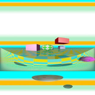
An ultra wide angle sample image |
Omnimax projection
The omnimax projection is a 180 degrees fisheye that has a reduced viewing angle in the vertical direction. In reality this projection is used to make movies that can be viewed in the dome-like Omnimax theaters. The image will look somewhat elliptical.
|
The omnimax projection diagram |
An omnimax camera sample image |
Note: The use of the angle keyword is irrelevant, the relative length of up and right vectors are what is important.
Panoramic projection
This projection is called "cylindrical equirectangular projection". It overcomes the degeneration problem of the perspective projection if the viewing angle approaches 180 degrees. It uses a type of cylindrical projection to be able to use viewing angles larger than 180 degrees with a tolerable lateral-stretching distortion. The angle keyword is used to determine the viewing angle.
|
The panoramic projection diagram |
A panoramic camera sample image |
Note: The angle keyword is irrelevant. The relative length of direction, up and right vectors are important as they define the lengths of the 3 axis of the ellipsoid. With identical length and orthogonal vectors (both strongly recommended, unless used on purpose), it's identical to a spherical camera with angle 180,90.
Cylindrical projection
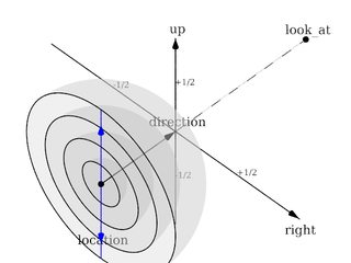
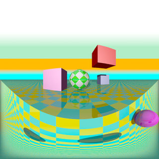
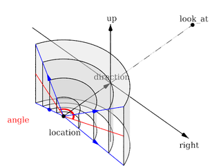
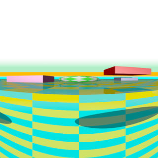
Using this projection the scene is projected onto a cylinder. There are four different types of cylindrical projections depending on the orientation of the cylinder and the position of the viewpoint. An integer value in the range 1 to 4 must follow the cylinder keyword. The viewing angle and the length of the up or right vector determine the dimensions of the camera and the visible image. The characteristics of different types are as follows:
- vertical cylinder, fixed viewpoint
- horizontal cylinder, fixed viewpoint
- vertical cylinder, viewpoint moves along the cylinder's axis
- horizontal cylinder, viewpoint moves along the cylinder's axis
|
The type 1 cylindrical projection diagram |
A type 1 cylindrical camera sample image |
|
The type 2 cylindrical projection diagram |
A type 2 cylindrical camera sample image |
|
The type 3 cylindrical projection diagram |
A type 3 cylindrical camera sample image |
|
The type 4 cylindrical projection diagram |
A type 4 cylindrical camera sample image |
Spherical projection
Using this projection the scene is projected onto a sphere.
The syntax is:
camera {
  spherical
  [angle HORIZONTAL [VERTICAL]]
  [CAMERA_ITEMS...]
  }
The first value after angle sets the horizontal viewing angle of the camera. With the optional second value, the vertical viewing angle is set: both in degrees. If the vertical angle is not specified, it defaults to half the horizontal angle.
The spherical projection is similar to the fisheye projection, in that the scene is projected on a sphere. But unlike the fisheye camera, it uses rectangular coordinates instead of polar coordinates; in this it works the same way as spherical mapping (map_type 1).
This has a number of uses. Firstly, it allows an image rendered with the spherical camera to be mapped on a sphere without distortion (with the fisheye camera, you first have to convert the image from polar to rectangular coordinates in some image editor). Also, it allows effects such as "environment mapping", often used for simulating reflections in scanline renderers.
|
The spherical projection diagram |
A spherical camera sample image |
Note: The lengths of the direction, up and right vectors are irrelevant. Angle is the important setting, and it gets two values separated by a comma: the first is the horizontal angle, the second is the vertical angle. Both values can reach 360. If the second value is missing, it is set to half the value of the first.
User defined projection
New to version 3.7.1 a user defined camera capability was added. Like the mesh camera the user_defined camera allows complete control over ray origin and direction, with the advantage of not having to actually load a mesh to function. It's inner workings are also less constrained than the mesh camera.
In addition to being able to duplicate existing camera types, this mechanism can also be easily used for other arbitrary camera formats waiting to be integrated into POV-Ray. This includes light probe style, angular, cube mapping, side-by-side stereo-grams, Omni-Directional Stereo (ODS), Mercator, and other map projections.
In the examples below the specified functions are passed x,y screen coordinates (or u,v) as parameters, ranging from -0.5 (left/bottom) to 0.5 (right/top), respectively.
// Basic orthographic
#declare Camera01 = camera {
    user_defined
    location {
      function { x }
      function { y }
      function { -5 }
    }
    direction {
      function { 0 }
      function { 0 }
      function { 1 }
    }
}

// Only direction functions specified
#declare Camera01 = camera {
    user_defined
    direction {
      function { x }
      function { y }
      function { 1 }
    }
    location  <0,0,-2>
    rotate    y*5
}

// Only location functions specified
#declare Camera01 = camera {
    user_defined
    location {
      function { x }
      function { y }
      function { -5 }
    }
    look_at   <0,0,1>
}
See the sample scene file ~scenes\camera\user_defined.pov for additional usage.
Focal Blur
POV-Ray can simulate focal depth-of-field by shooting a number of sample rays from jittered points within each pixel and averaging the results.
To turn on focal blur, you must specify the aperture keyword followed by a float value which determines the depth of the sharpness zone. Large apertures give a lot of blurring, while narrow apertures will give a wide zone of sharpness.
Note: While this behaves as a real camera does, the values for aperture are purely arbitrary and are not related to f-stops.
You must also specify the blur_samples keyword followed by an integer value specifying the maximum number of rays to use for each pixel. More rays give a smoother appearance but is slower. By default no focal blur is used, i. e. the default aperture is 0 and the default number of samples is 0.
The center of the zone of sharpness is specified by the focal_point vector. The zone of sharpness is a plane through the focal_point and is parallel to the camera. Objects close to this plane of focus are in focus and those farther from that plane are more blurred. The default value is focal_point<0,0,0>.
Although blur_samples specifies the maximum number of samples, there is an adaptive mechanism that stops shooting rays when a certain degree of confidence has been reached. At that point, shooting more rays would not result in a significant change.
Extra samples are generated in a circular rather than square pattern when blur_samples is not set to either 4, 7, 19 or 37, leading to a circular rather than square bokeh. The extra samples are generated from a Halton sequence rather than a random stream. You can also optionally specify a minimum number of samples to be taken before testing against the confidence and variance settings. The default is 4, if the blur_samples maximum is less than 7, otherwise the default is 7, to provide a means to get rid of stray non-blurred pixels.
The syntax is:
blur_samples [ MIN_SAMPLES, ] MAX_SAMPLES
The confidence and
variance keywords are followed by float values to control the adaptive function. The confidence value is used to determine when the samples seem to be close enough to the correct color. The variance value specifies an acceptable tolerance on the variance of the samples taken so far. In other words, the process of shooting sample rays is terminated when the estimated color value is very likely (as controlled by the confidence probability) near the real color value.
Since the confidence is a probability its values can range from 0 to less than 1 (the default is 0.9, i. e. 90%). The value for the variance should be in the range of the smallest displayable color difference (the default is 1/128). If 1 is used POV-Ray will issue a warning and then use the default instead.
Rendering with the default settings can result in quite grainy images. This can be improved by using a lower variance. A value of 1/10000 gives a fairly good result (with default confidence and blur_samples set to something like 100) without being unacceptably slow.
Larger confidence values will lead to more samples, slower traces and better images. The same holds for smaller variance thresholds.
Focal blur can also support a user-defined bokeh using the following syntax:
camera {
  // ... focal blur camera definition
  bokeh {
    pigment { ... }
    }
  }
If bokeh is specified, focal blur will use a custom sampling sequence based on the specified pigment's brightness in the range <0,0,0> to <1,1,0> i.e. the unit square in the XY plane.
Camera Ray Perturbation
The optional normal may be used to assign a normal pattern to
the camera. For example:
camera{
  location Here
  look_at There
  normal { bumps 0.5 }
  }
All camera rays will be perturbed using this pattern. The image will be distorted as though you were looking through bumpy glass or seeing a reflection off of a bumpy surface. This lets you create special effects. See the animated scene camera2.pov for an example. See Normal for information on normal patterns.
Camera Identifiers
Camera identifiers may be declared to make scene files more readable and to parameterize scenes so that changing a single declaration changes many values. You may declare several camera identifiers if you wish. This makes it easy to quickly change cameras. An identifier is declared as follows.
CAMERA_DECLARATION:
  #declare IDENTIFIER = CAMERA |
  #local IDENTIFIER = CAMERA
Where IDENTIFIER is the name of the identifier up to 40 characters long and CAMERA is any valid camera statement. See #declare vs. #local for information on identifier scope. Here is an example...
#declare Long_Lens =
camera {
  location -z*100
  look_at <0,0,0>
  angle 3
  }

#declare Short_Lens =
camera {
  location -z*50
  look_at <0,0,0>
  angle 15
  }

camera {
  Long_Lens  // edit this line to change lenses
  translate <33,2,0>
  }
Note: Only camera transformations can be added to an already declared camera. Camera behaviour changing keywords are not allowed, as they are needed in an earlier stage for resolving the keyword order dependencies.
