User:Wfpokorny
- the above prism additions have been added with a few minor changes. --jholsenback
- The following is a first draft update for http://wiki.povray.org/content/Reference:Density_File_Pattern and the df3 file --wfpokorny
- NOTE!!! It is written assuming my local fixes for the 32bit df3 write will be adopted for 3.7.1, but I've yet to open the issue and generate the associated pull request.
- -----------------------------------------------------------
The density_file pattern is a 3-D bitmap pattern that
occupies a unit cube from location <0,0,0> to <1,1,1>. The data
file is a raw binary file format created for POV-Ray called df3
format. The syntax provides for the possibility of implementing other formats
in the future. This pattern was originally created for use with
halo or media, but it may be used anywhere any pattern may
be used. The syntax is:
pigment {
  density_file df3 "filename.df3"
  [interpolate Type] [PIGMENT_MODIFIERS...]
  }
where "filename.df3" is a file name of the
data file.
As a normal pattern, the syntax is
normal {
  density_file df3 "filename.df3" [, Bump_Size]
  [interpolate Type]
  [NORMAL_MODIFIERS...]
  }
The optional float Bump_Size should follow the file
name and any other modifiers follow that.
The density pattern occupies the unit cube regardless of the dimensions in voxels. It remains at 0.0 for all areas beyond the unit cube. The data in the range of 0 to 255, in case of 8 bit resolution, are scaled into a float value in the range 0.0 to 1.0.
The interpolate keyword may be specified to add interpolation
of the data. The default value of zero specifies no interpolation. A value of
one specifies tri-linear interpolation, a value of two specifies tri-cubic
interpolation.
Note: Currently only the no interpolation mode of 0 is truly voxel centered. Other modes are grid centered causing a half voxel width/height shift down and to the left.
Note: Interpolation for data at the unit cube's sides wraps for modes other than 0. Due this it may be best to add buffer voxels along all sides of the cube in interpolation modes 1 and 2.
The df3 files can be created with a utility function called ARRAYS_WriteDF3() shipped as part of the arrays.inc file and so can be used as depth maps, displacement maps or to store positional information frame to frame in an animation. The following short example shows the df3 file used to store 32bitTemplate:New.3.7.1 values.
#version 3.71; // Prior lacked 32 bit write.
global_settings { assumed_gamma 1 }

#include "DF3_updated_arrays.inc"

#macro PrintDF3(_X,_Y,FileName)
   #local Pigment_df3_32 = pigment{
     density_file df3 FileName interpolate 0
   }
   #local Fn_df3_32 = function{ pigment{ Pigment_df3_32 }}

   // Access and print df3 values in x=row, y=column order
   #local Dx       =1/_X;
   #local DxVoxCtr =Dx/2;
   #local Dy       =1/_Y;
   #local DyVoxCtr =Dy/2;
   #debug "\n-------------------"
   #for (Y,0,_Y-1)
     #debug "\n"
     #for (X,0,_X-1)
       #local Xi=(X*Dx)+DxVoxCtr;
       #local Yi=(Y*Dy)+DyVoxCtr;
       #debug concat(str(Fn_df3_32(Xi,Yi,0.50).red,2,2)," ")
     #end
   #end
   #debug "\n-------------------\n"
#end

#declare Xn=10;
#declare Yn=5;

#declare AryXY =
 array[Xn][Yn]
 {//   x
  //   | y->
  //   v
     {0.01,0.02,0.03,0.04,0.05},
     {0.11,0.12,0.13,0.14,0.15},
     {0.21,0.22,0.23,0.24,0.25},
     {0.31,0.32,0.33,0.34,0.35},
     {0.41,0.42,0.43,0.44,0.45},
     {0.51,0.52,0.53,0.54,0.55},
     {0.61,0.62,0.63,0.64,0.65},
     {0.71,0.72,0.73,0.74,0.75},
     {0.81,0.82,0.83,0.84,0.85},
     {0.91,0.92,0.93,0.94,0.95}
 }

#declare FileName="bits32.df3";
ARRAYS_WriteDF3(AryXY,FileName,32)
PrintDF3(Xn,Yn,FileName)

#declare AryXY[0][2]=0;
#declare AryXY[1][2]=0;
#declare AryXY[2][2]=0;
#declare AryXY[3][2]=0;
#declare AryXY[4][2]=0;

ARRAYS_WriteDF3(AryXY,FileName,32)
PrintDF3(Xn,Yn,FileName)

#declare AryXY[5][2]=1;
#declare AryXY[6][2]=1;
#declare AryXY[7][2]=1;
#declare AryXY[8][2]=1;
#declare AryXY[9][2]=1;

ARRAYS_WriteDF3(AryXY,FileName,32)
PrintDF3(Xn,Yn,FileName)
When run, the code above prints the following three blocks of values accessed via functions based upon a df3 file pigment using interpolation 0 showing repeated cycles of value storage, value modification and display. With the value display arranged in x-horizontal and y-vertical order.
-------------------
0.01 0.11 0.21 0.31 0.41 0.51 0.61 0.71 0.81 0.91
0.02 0.12 0.22 0.32 0.42 0.52 0.62 0.72 0.82 0.92
0.03 0.13 0.23 0.33 0.43 0.53 0.63 0.73 0.83 0.93
0.04 0.14 0.24 0.34 0.44 0.54 0.64 0.74 0.84 0.94
0.05 0.15 0.25 0.35 0.45 0.55 0.65 0.75 0.85 0.95
-------------------

-------------------
0.01 0.11 0.21 0.31 0.41 0.51 0.61 0.71 0.81 0.91
0.02 0.12 0.22 0.32 0.42 0.52 0.62 0.72 0.82 0.92
0.00 0.00 0.00 0.00 0.00 0.53 0.63 0.73 0.83 0.93
0.04 0.14 0.24 0.34 0.44 0.54 0.64 0.74 0.84 0.94
0.05 0.15 0.25 0.35 0.45 0.55 0.65 0.75 0.85 0.95
-------------------

-------------------
0.01 0.11 0.21 0.31 0.41 0.51 0.61 0.71 0.81 0.91
0.02 0.12 0.22 0.32 0.42 0.52 0.62 0.72 0.82 0.92
0.00 0.00 0.00 0.00 0.00 1.00 1.00 1.00 1.00 1.00
0.04 0.14 0.24 0.34 0.44 0.54 0.64 0.74 0.84 0.94
0.05 0.15 0.25 0.35 0.45 0.55 0.65 0.75 0.85 0.95
-------------------
See too the sample scenes for data file include\spiral.df3,and
the scenes which use it: ~scenes\textures\patterns\densfile.pov,
~scenes\interior\media\galaxy.pov for examples.
df3 file format
- Header:
- The
df3format consists of a 6 byte header of three 16-bit integers with high order byte first. These three values give the x,y,z size of the data in pixels (or more appropriately called voxels ). - Data:
- The header is followed by x*y*z unsigned integer bytes of data with a resolution of 8, 16 or 32 bit. The data are written with high order byte first (big-endian). The resolution of the data is determined by the size of the df3-file. That is, if the file is twice (minus header, of course) as long as an 8 bit file then it is assumed to contain 16 bit ints and if it is four times as long 32 bit ints.
- -----------------------------------------------------------
Spindle Torus
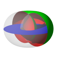
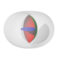
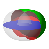
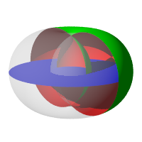
Template:New.3.7.1 A torus with a minor radius greater than the major radius
(aka spindle torus) will self-intersect in a spindle-shaped region.
The behaviour with respect to the spindle can be controlled by specifying
either of the difference, intersection,
merge or union keywords, which act similar to the
corresponding CSG operations:
- Using the
differencekeyword, the self-intersecting portion is cut away from the torus, so that the spindle volume is considered outside the primitive; the spindle surface is visible (provided you cut open the torus, or make it semi-transparent). - Using the
intersectionkeyword, the resulting shape consists of only the self-intersecting portion, so that only the spindle volume is considered inside the primitive, and only the spindle surface is visible. - Using the
mergekeyword, the surface within the self-intersecting portion is hidden, so that the spindle surface is not visible; the spindle volume is considered inside the primitive. - Using the
unionkeyword, the entire torus surface remains visible and the spindle volume is considered inside the primitive (this is the default).
In a non-spindle torus, the intersection keyword will cause a
"possible parse error" warning and make the torus invisible, while the other
spindle mode keywords will have no effect whatsoever.
Note: The difference spindle mode
does not affect the behaviour with respect to the
interior_texture keyword. An
interior_texture will always be applied to the side of the spindle
surface facing the spindle volume.
cutaway view of spindle torus using the |
|||
Sturm
Calculations for all higher order polynomials must be very accurate. If the
torus renders improperly you may add the keyword sturm to use
POV-Ray's slower-yet-more-accurate Sturmian root solver.


